Proportional valve

a proportional valve and valve element technology, applied in the direction of fluid pressure control, lighting and heating apparatus, instruments, etc., can solve the problems of reducing controllability and moving the valve element by itself to open or clos

Inactive Publication Date: 2005-03-15
TGK
View PDF6 Cites 32 Cited by
  • Summary
  • Abstract
  • Description
  • Claims
  • Application Information

AI Technical Summary

Benefits of technology

[0011]The present invention was created in view of the above circumstances, and an object thereof is t

Problems solved by technology

Thus, the back pressure cancellation fails to function properly, giving rise to a problem that the valve element moves by itself to open or close due to the difference between the pressure receiving areas.
Since the labyrinth seal

Method used


Image

  • Proportional valve
  • Proportional valve
  • Proportional valve

Examples


second embodiment

n">[0018]FIG. 5 is a longitudinal sectional view showing a de-energized state of a proportional valve according to a

[0019]FIG. 6 is a longitudinal sectional view showing an energized state of the proportional valve of the second embodiment.

third embodiment

[0020]FIG. 7 is a longitudinal sectional view showing a de-energized state of a proportional valve according to a

DESCRIPTION OF THE PREFERRED EMBODIMENTS

[0021]Embodiments of the present invention will be hereinafter described in detail with reference to the drawings, wherein the invention is applied, by way of example, to a pressure reducing device of an automotive air conditioning system.

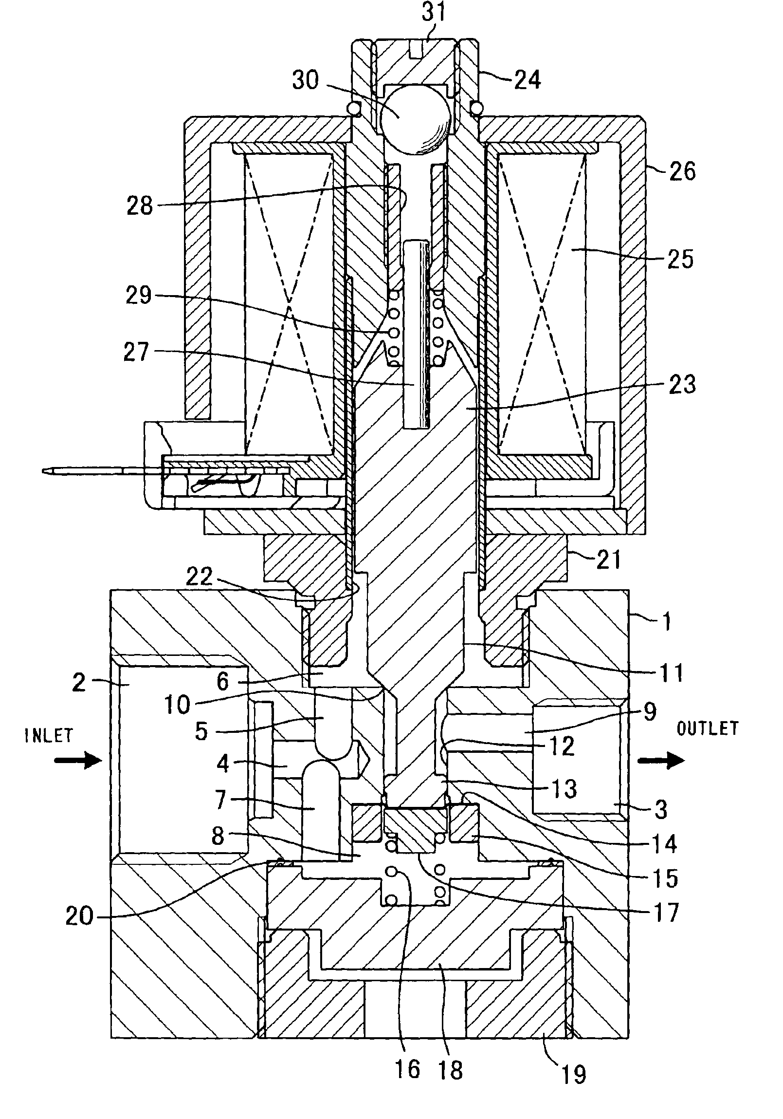
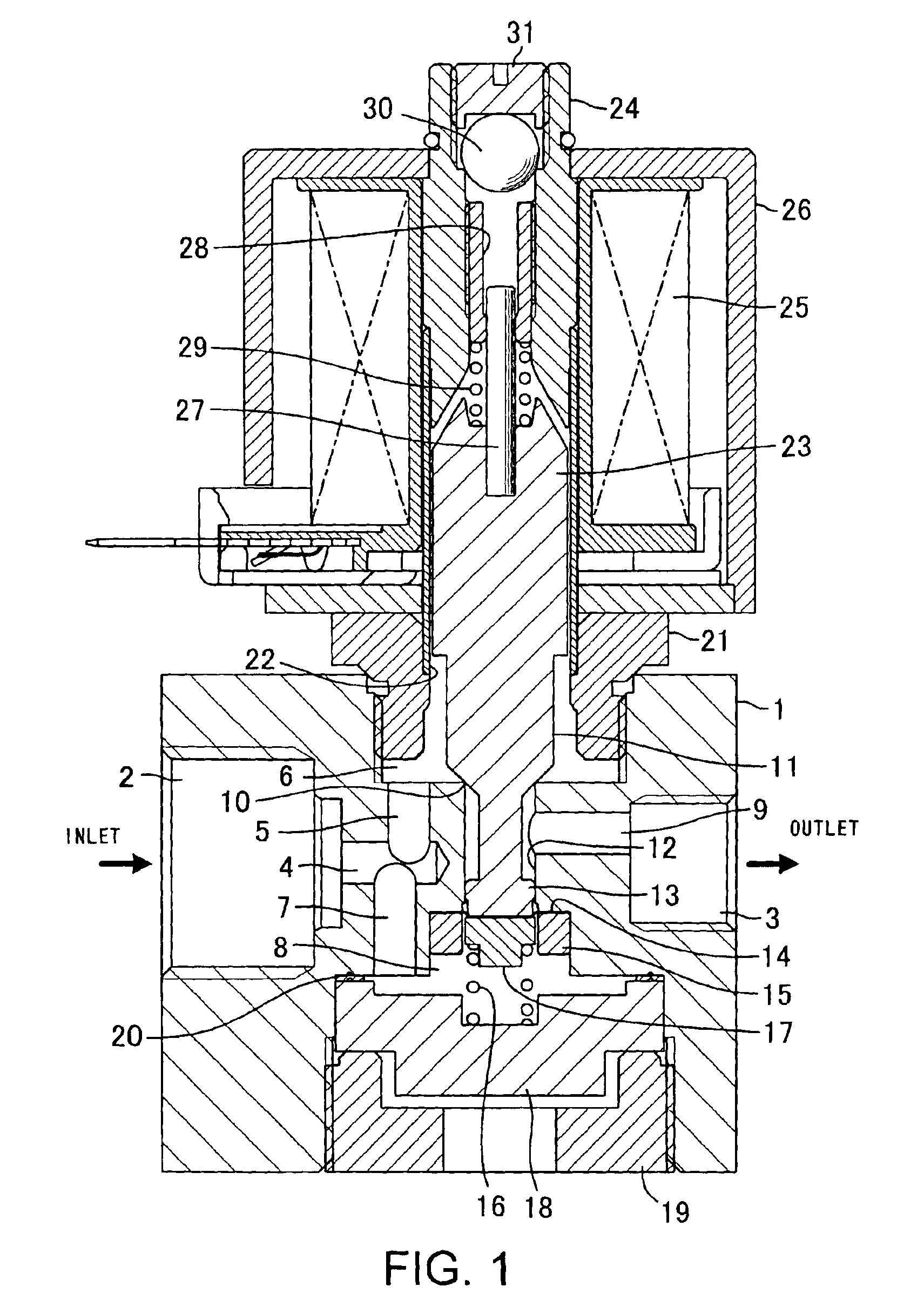
[0022]FIG. 1 is a longitudinal sectional view showing a de-energized state of a proportional valve according to a first embodiment, FIG. 2 is an enlarged sectional view of a principal part appearing in FIG. 1, FIG. 3 is a diagram illustrating change in pressure receiving area of a diaphragm, and FIG. 4 is a longitudinal sectional view showing an energized state of the proportional valve of the first embodiment.

[0023]A proportional valve according to the present invention has an inlet port 2 for receiving high-pressure refrigerant and an outlet port 3, the ports being formed in respective side faces...

first embodiment

[0039]The valve element 11 is formed integrally with the piston 13, thus constituting a one-piece body, and the pressure receiving portion of the piston 13 is configured in the same manner as that of the piston of the proportional valve of the The stopper 17 disposed in contact with the diaphragm 14 is urged in the valve opening direction by a spring 33 but receives no urging force from the solenoid when the solenoid is de-energized, so that the proportional valve remains fully open. The spring force of the spring 33 is adjusted by an adjusting screw 34 screwed into the body 1.

[0040]The diaphragm 14 is mounted in a displaced state such that when the valve element 11 is seated on the valve seat 10, the diaphragm 14 has the largest effective pressure-receiving area equal to the effective pressure-receiving area of the seated valve element 11, and that when the proportional valve is fully open as shown in FIG. 7, the diaphragm 14 has an effective pressure-receiving area corresponding ...


PUM


Abstract

The object of the present invention is to provide a proportional valve which does not open or close by itself and is free of internal leakage. A valve element is formed integrally with a piston having a cross-sectional area equal to that of a valve hole constituting a valve seat, and a diaphragm having an outer peripheral portion secured to a body by a holder is disposed in contact with a pressure-receiving end face of the piston. The diaphragm is mounted in a displaced state such that when the valve element is seated on the valve seat, the pressure receiving area of the diaphragm is at a maximum and is equal to that of the valve element. Change in the pressure receiving area of the valve element corresponding to the lift amount thereof is canceled out by change in the pressure receiving area of the diaphragm corresponding to the amount of displacement thereof, thus preventing the valve from opening or closing by itself due to the difference between the pressure receiving areas. Also, a sliding portion of the piston is shut off by the diaphragm, whereby internal leakage can be completely prevented.

Description

CROSS-REFERENCES TO RELATED APPLICATIONS, IF ANY[0002]This application claims priority of Japanese Application No. 2002-259474 filed on Sep. 5, 2002 and entitled “Proportional Valve”.BACKGROUND OF THE INVENTION[0003](1) Field of the Invention[0004]The present invention relates to a proportional valve, and more particularly, to a solenoid-operated proportional valve whose lift amount varies in proportion to a value of current supplied to the solenoid.[0005](2) Description of the Related Art[0006]As a refrigerating cycle of an automotive air conditioning system, for example, there has been known a configuration wherein high-temperature, high-pressure gaseous refrigerant compressed by a compressor is condensed or cooled by a condenser or a gas cooler, the condensed or cooled refrigerant is turned into low-temperature, low-pressure refrigerant by a pressure reducing device, the low-temperature refrigerant is evaporated by an evaporator, the evaporated refrigerant is separated into gas a...

Claims


Application Information

Patent Timeline
IPC IPC(8): F25B41/06G05D16/20B60H1/32F16K31/06
CPCF25B41/062G05D16/2013F25B2341/065Y02B30/72F25B2600/2505G05D16/2022Y02B30/70F25B41/34F25B41/335F25B41/345
Inventor HIROTA, HISATOSHI
Owner TGK
Why Eureka
Try Eureka