
Modular cast independent front suspension subframe

a subframe and modular technology, applied in the field of vehicle suspensions, can solve the problems of less space and relatively light subframe, and achieve the effects of reducing assembly time and cost, improving dimensional control of suspension and steering mounting points, and convenient manufacture and production

Inactive Publication Date: 2005-03-15
DANA HEAVY VEHICLE SYSTEMS GROUP LLC
View PDF42 Cites 41 Cited by
  • Summary
  • Abstract
  • Description
  • Claims
  • Application Information

AI Technical Summary

Benefits of technology

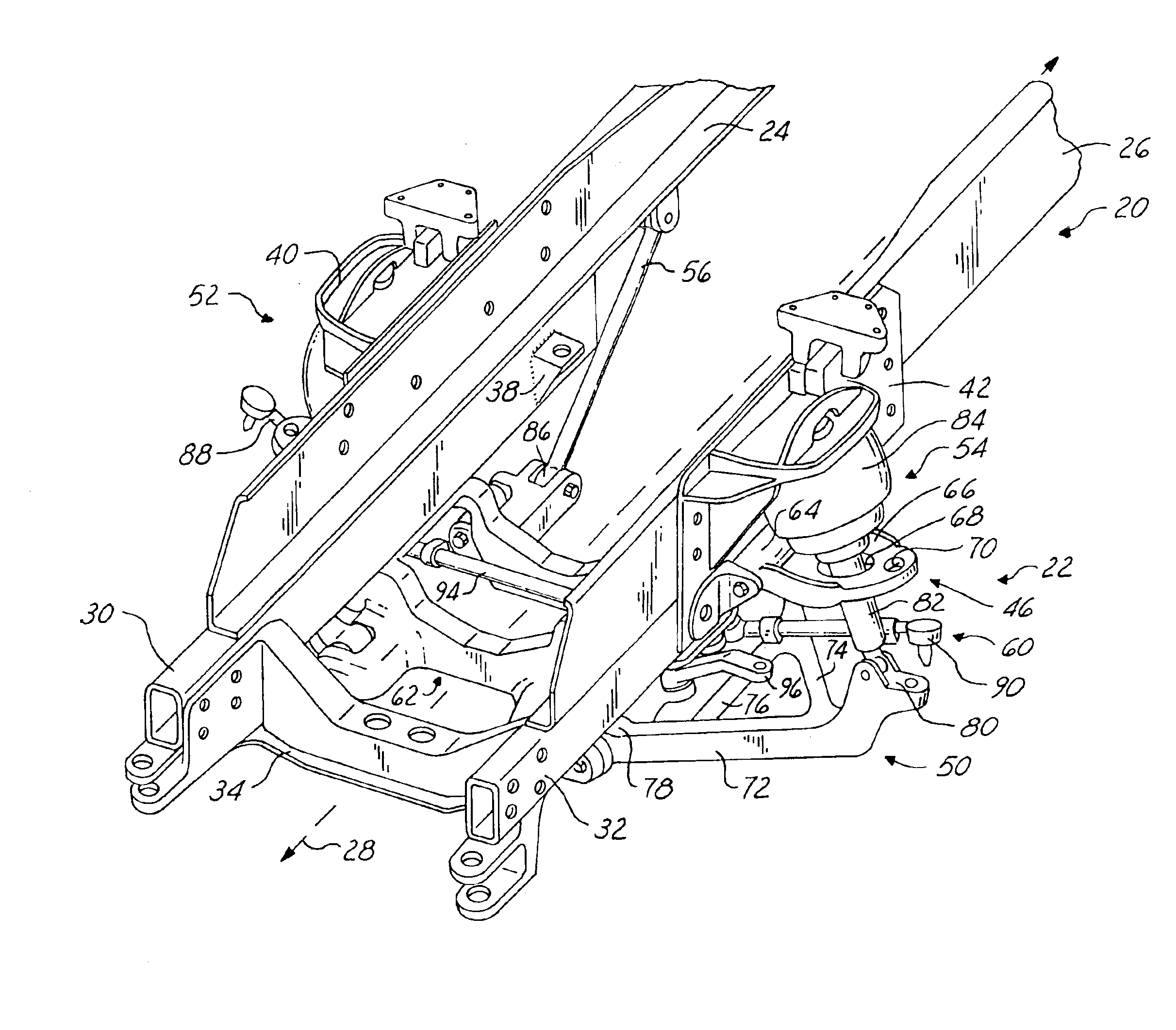
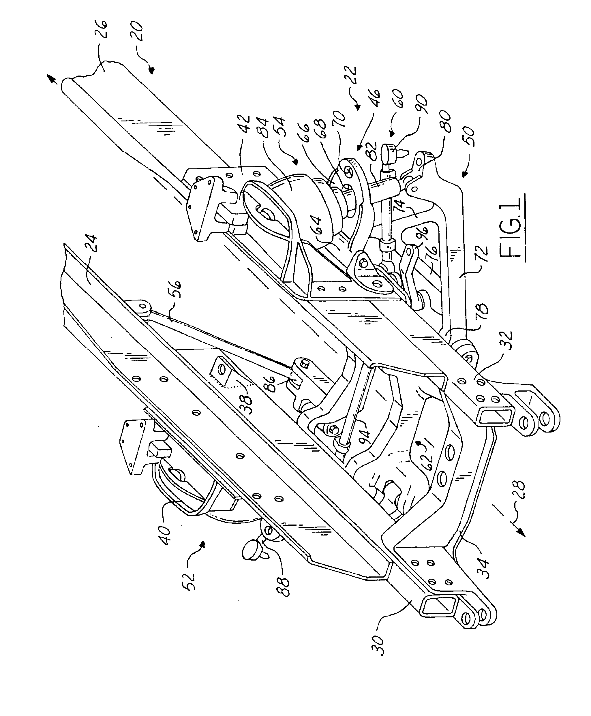
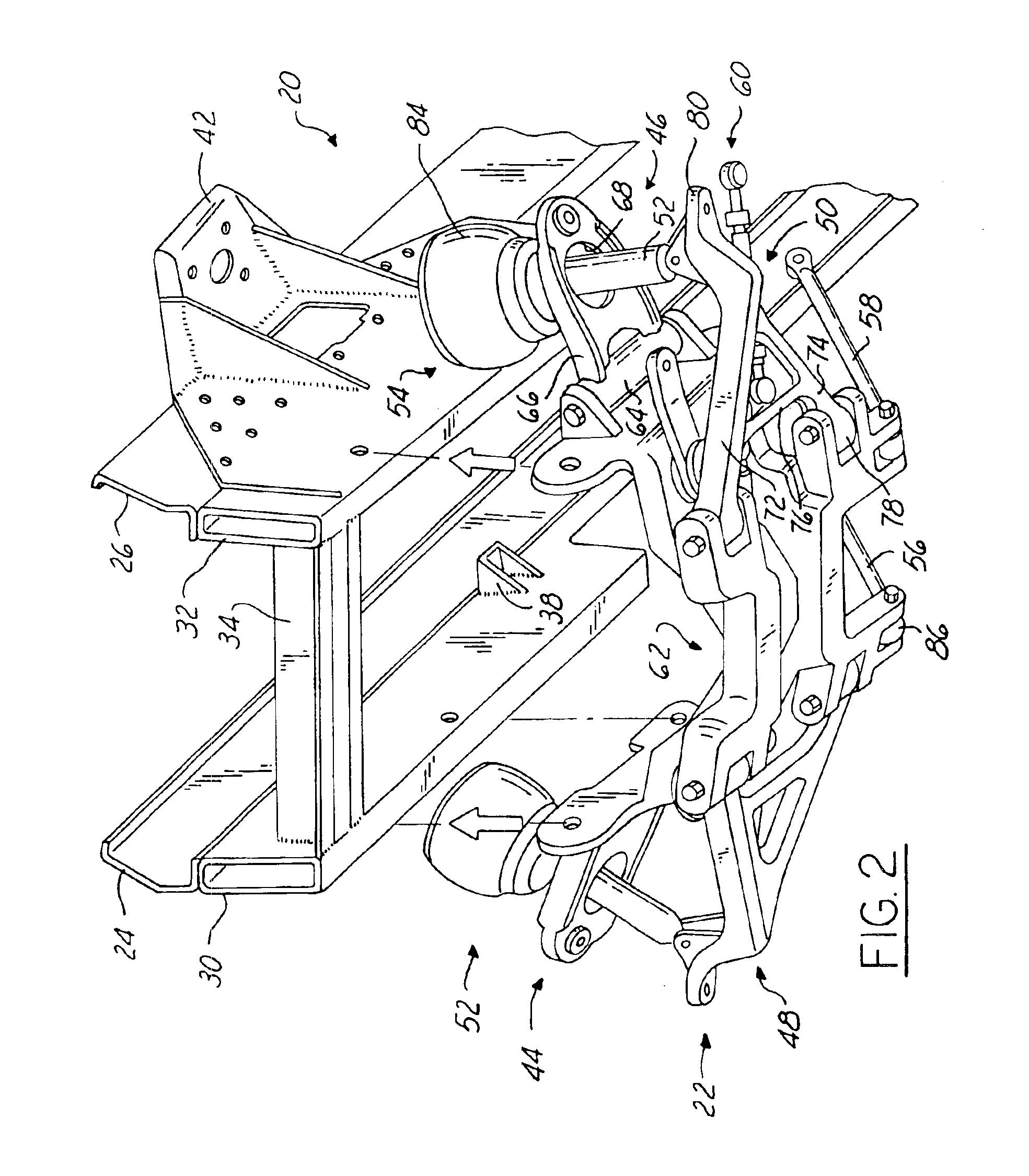
The present invention provides a subframe for heavy trucks that has several advantages over conventional subframes. The subframe is a unitary member with no bolts, welds, or other fasteners required, which reduces assembly time and cost and ensures better dimensional control of suspension and steering mounting points. The subframe is relatively light and requires less space. The subframe also allows relatively easy manufacture and production of a subassembly including many of the conventional suspension and steering components.

Problems solved by technology

Third, the subframe is relatively light as compared to conventional subframes and requires less space.

Method used


Image

  • Modular cast independent front suspension subframe
  • Modular cast independent front suspension subframe
  • Modular cast independent front suspension subframe

Examples


second embodiment

Referring now to FIG. 8, a subframe 166 in accordance with the present invention will be described. Like subframe 62, subframe 166 includes a pair of side members 168, 170 and a pair of cross members 172, 174.

Side members 168, 170 extend generally parallel to axis 28 when subframe 166 is mounted to frame 20 and are located inboard of the outboard ends of cross members 172, 174. Each of members 168, 170 includes a pair of intersecting support arms 176, 178 and 180, 182, respectively, extending therefrom in a generally outboard direction. Arms 176, 178 and 180, 182, respectively, include axially extending apertures 184 at the point of intersection configured to receive a screw, bolt, or other fastener to couple upper suspension control arms (not shown) thereto and allow pivoting motion of upper suspension control arms. Each of members 168, 170 also includes a pair of mounting flanges 186, 188 and 190, 192, respectively, extending therefrom in a direction generally perpendicular to axi...

third embodiment

Referring now to FIG. 9, a subframe 212 in accordance with the present invention will be described. Subframe 212 is substantially similar to subframe 62. Subframe 212, however, includes a cross member 214 that is integral with the other components of subframe 212. As illustrated in FIG. 9, member 214 is provided to support the vehicle engine and may take the place of cross member 34 of frame 20 shown in FIGS. 1-2. Member 214 extends generally transverse to axis 28. It should be understood that the size, shape, and configuration of member 214 may vary depending upon design requirements associated with the vehicle engine and frame 20.


PUM


Abstract

A suspension and steering subassembly for a heavy truck is provided including a subframe. The subframe includes first and second side members extending substantially in the direction of vehicle travel and first and second cross members extending substantially perpendicular to the direction of vehicle travel. The first and second cross members are integral with the first and second side members such that the subframe is a unitary member. The first and second side members and the first and second cross members are further configured to receive first and second lower suspension control arms, first and second upper suspension control arms, and a portion of the steering linkage for the vehicle. The subframe may further be configured to receive a steering gear and one or more strut rods to provide fore / aft support to the subframe.

Description

BACKGROUND OF THE INVENTION1. Field of the InventionThis invention relates to vehicle suspensions and, in particular, to a subframe for use in an independent front suspension system.2. Disclosure of Related ArtIt is conventional in motor vehicles having independent front suspensions to incorporate a subframe to increase the strength of the axle on which the suspension is employed. Conventional subframes used in heavy truck applications, however, have suffered from several drawbacks. First, most conventional subframes include numerous members that are coupled together using bolts, welds, or other fastening means. The assembly of these members into a single subframe makes dimensional control of mounting points for suspension and steering components relatively difficult thereby increasing wear on the suspension components and joints among other drawbacks. The assembly also increases the time and cost required to produce the subframe. Second, conventional subframes have generally been u...

Claims


Application Information

Patent Timeline
Patent Type & Authority Patents(United States)
IPC IPC(8): B60G11/28B60G11/26B60G7/02B62D21/11
CPCB60G7/02B62D21/11B60G11/28B60G2200/144B60G2200/44B60G2202/314B60G2204/143B60G2204/15B60G2204/43B60G2206/0114B60G2206/124B60G2206/60B60G2206/605B60G2206/8101B60G2300/026B60G2300/14B60G2300/38
Inventor ZIECH, JAMES F.ZEBOLSKY, MICHAEL L.
Owner DANA HEAVY VEHICLE SYSTEMS GROUP LLC
Learn More