
Slurpie hose connection

a technology of slurpie hose and hose body, which is applied in the direction of mechanical equipment, transportation and packaging, liquid transfer devices, etc., can solve the problems that perfumes may be detrimental to the quality of our air, and achieve the effect of quick and easy connection and quick installation

Active Publication Date: 2005-03-15
HUSKY
View PDF15 Cites 23 Cited by
  • Summary
  • Abstract
  • Description
  • Claims
  • Application Information

AI Technical Summary

Benefits of technology

Essentially, this invention is developed in two parts, a nozzle segment for interconnecting the hose and slurpie system to a nozzle, which includes means for interconnecting the fuel flow path through this connection, and into the nozzle, while simultaneously providing for a separate and distinct vapor return path, for the retransmission and return of vapors back to the dispenser, and underground storage, all of which can be quickly and facilely connected together, when the hose and nozzle are assembled for usage. The second part of the system is the hose connecting component, which mates with the nozzle part, and can be quickly installed, fastened in place, to furnish a prompt interconnect of the fuel dispensing hose, with the nozzle, as readied for installation and usage.
In addition, a conveniently available nut, threadedly or pressure engages within the open end of the nozzle, can be threaded into tightness, and afford and assure the sealed interconnection between the various components of this connector, and the coaxial hose, to furnish a fool proof operation.
Still another object of this invention is to provide for means for interconnecting a coaxial fuel dispensing hose to a nozzle, with a minimum of effort.

Problems solved by technology

Environmentalists have stated that these types of fumes may be detrimental to the quality of our air.
But, when these types of techniques are used to recover vapors, due to the condensability of such fuels, there is always the likelihood that the vapors may contain a certain amount of the fuel moisture, which may condense or coagulate into droplets, and accumulate in the dispensing hose, rather than get returned back to the dispenser, and to underground storage, as desired.
As a result, it is necessary to keep these accumulated pockets of liquid fuel from blocking the vapor return pass within the coaxial fuel hose, which would otherwise prevent the return of vapors, and block their transmission back into storage.
When that occurs, the vapors overflow from the nozzle, or from the vehicle, the return suction is eliminated, meaning that such vapors are disseminated into atmosphere, not only to present the alleged detriments claimed by the environmentalists, but also probably in violation of the various laws that have now been promulgated to require the collection of such vapors.

Method used


Image

  • Slurpie hose connection
  • Slurpie hose connection
  • Slurpie hose connection

Examples


Embodiment Construction

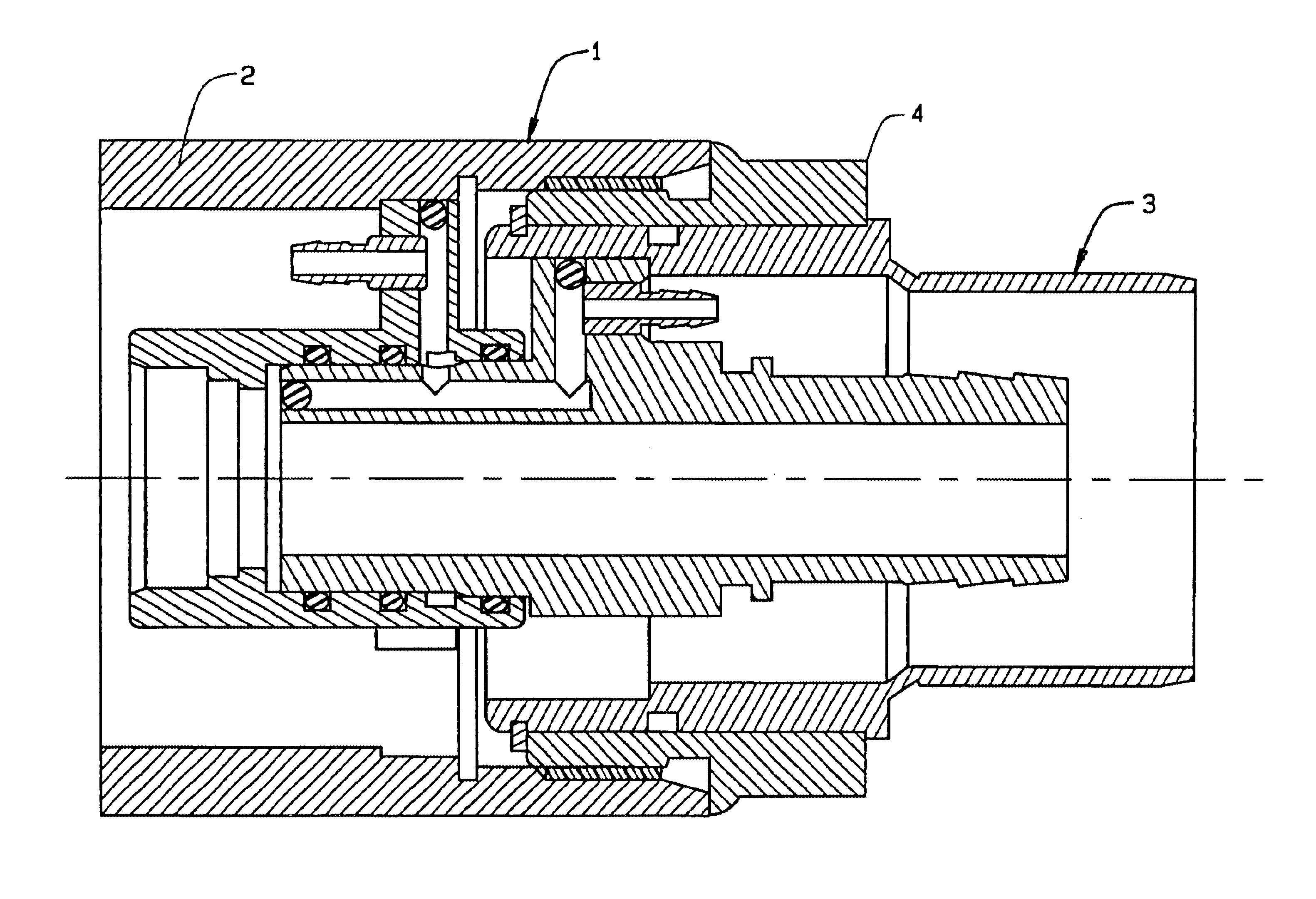
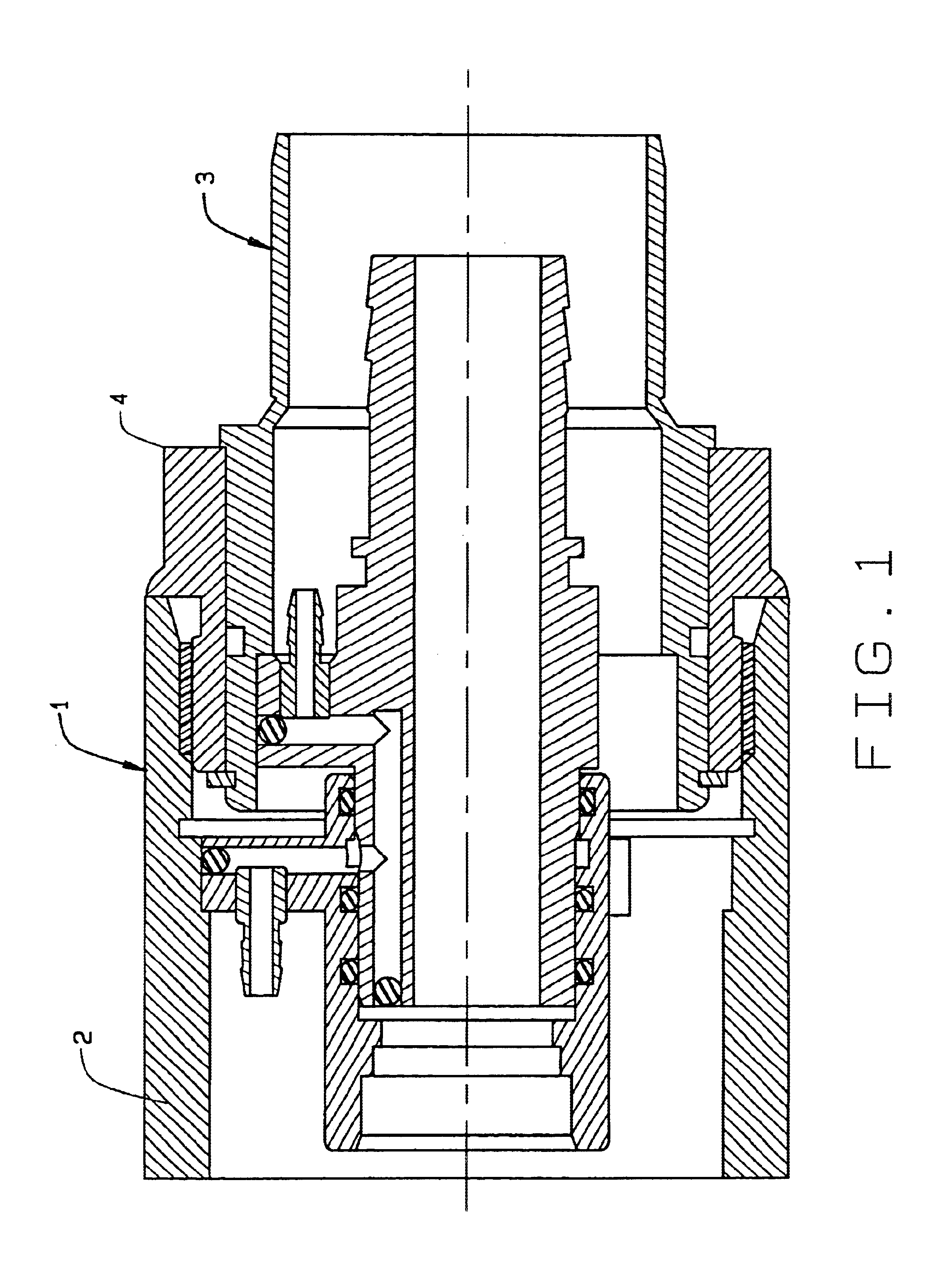
In referring to the drawings, and in particular FIG. 1, the connection 1 of this invention, is readily disclosed mounted partially within the back end 2 of the fuel dispensing nozzle, providing the means for connection of the coaxial hose, as attach thereto, as at 3. A type of nozzle nut 4 threadedly or otherwise engages within the back end of the nozzle handle, as can be noted, to provide for the tight and secure retention of these components altogether, via the connection 1, as can be seen.

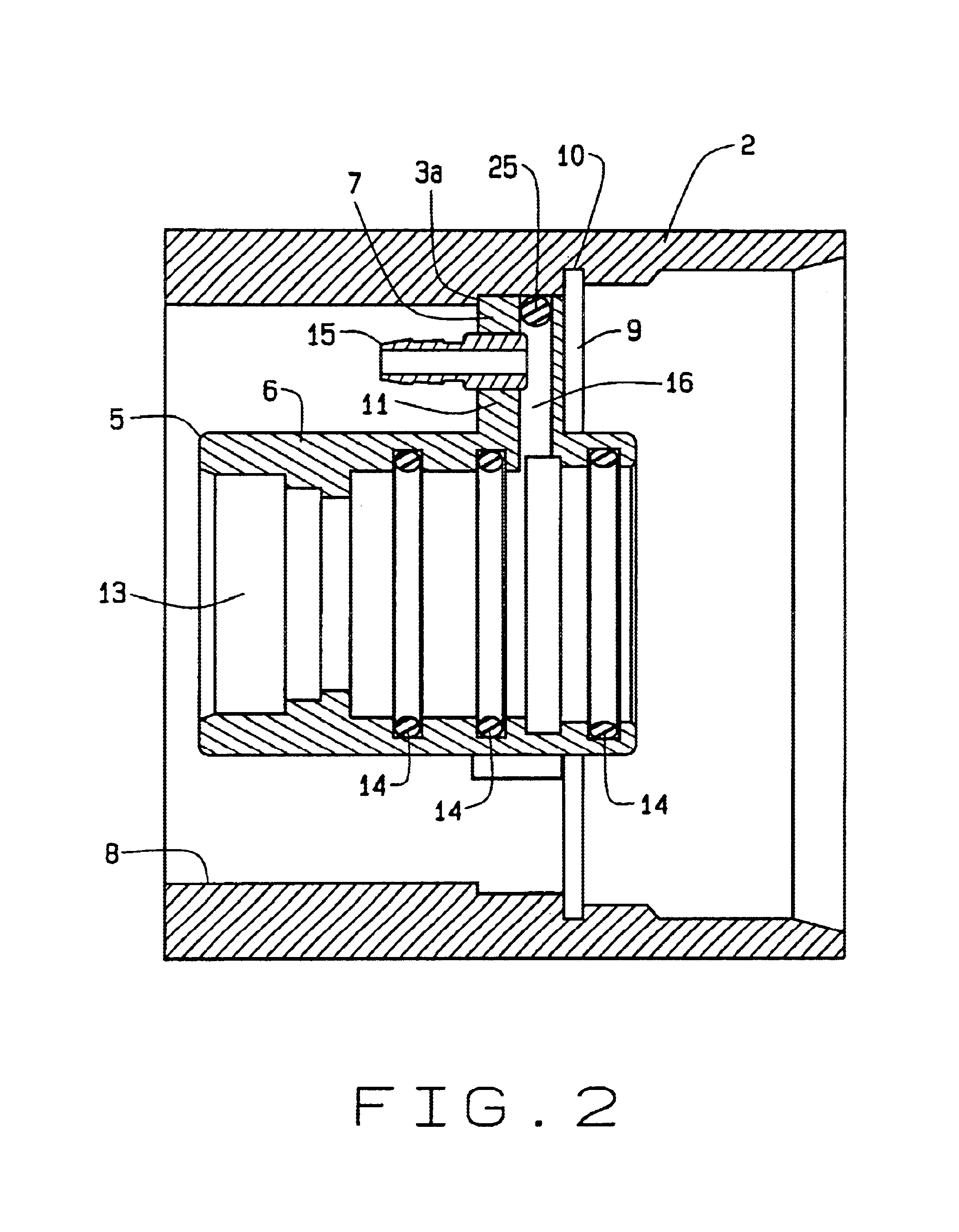
As can be seen internally of the nozzle hose connection, and referring also to FIG. 2, therein is disclosed that part of the connector 1 which is contained within the nozzle, as can be noted at 5. That particular component includes a cylindrical portion 6 having an integral flange 7 that extends radially, and which is inserted within the nozzle handle 2 to the extent where it abuts against a shoulder 3a around the inner perimeter of the opening 8 contained internally of the nozzle handle. This p...


PUM


Abstract

A slurpie hose connection, for attachment between the coaxial hose and the back end of a fuel dispensing nozzle, including two parts, a connector part that fits within the back end of the nozzle, a hose part that secures with the leading edge of the hose, such that when these two parts are brought together, and pushed into sealed engagement, a nut is fastened within the back end of the nozzle, to tightly and snuggly secure the hose connection together, available for prompt usage. A slurpie tube may fasten to tube fittings and extend forwardly in the nozzle, as known, and extend to the bottom of the coaxial hose, to act as a slurpie to remove any accumulated or condensed fuel, from this location, and to prevent its blockage of the return of vapors to the dispenser and for underground storage.

Description

BACKGROUND OF THE INVENTIONAs is well known in the art, environmental requirements, over the past decade or two, have made it essential that vapors and fumes generated during fuel dispensing, particularly at the myriad of service stations, be collected, at a high degree of efficiency, to prevent the entrance of such fumes into the atmosphere. Environmentalists have stated that these types of fumes may be detrimental to the quality of our air.As a result, many different types of devices have been constructed, formulated, and which function essentially to recover a large part of the gasoline vapors, from the interface between the service station dispenser, the nozzle, and where it inserts into the automobile fill tank, in an effort to collect the generated vapors, and return or pump them back into the underground storage facility, in an effort to reduce such pollutants.These types of vapor recovery systems may include pumps within the dispenser, that suck the vapors from the region of...

Claims


Application Information

Patent Timeline
IPC IPC(8): B67D5/01B67D5/04F16L39/00B67D7/04
CPCB67D7/0488F16L39/02F16L39/005
Inventor COATES, GORDON R.
Owner HUSKY
Learn More