E-frame and dolly system for stocking production lines

a technology of production lines and dolly systems, applied in the direction of transportation items, loading/unloading vehicle arrangment, refuse collection, etc., can solve problems such as wasting effort, creating safety concerns, and disrupting even the most carefully planned drop off sequen

Inactive Publication Date: 2005-03-15
FORD MOTOR CO
View PDF16 Cites 42 Cited by
  • Summary
  • Abstract
  • Description
  • Claims
  • Application Information

AI Technical Summary

Benefits of technology

According to one aspect of the present invention, a component part container delivery rack system for use in manufacturing operations is provided. The system includes a component part container with at least one dolly for supporting the component part container. The dolly is movably supported on a first set of wheels. A frame is supported on a second set of wheels and includes a front end, back end, and at least two compartments that are open on at least one side extending between the front and back ends. A locking element selectively engages one of the dollies to lock the dolly into one of the compartments during transport of the dolly by the frame. The dolly is configured to be removably received in one of the compartments.

Problems solved by technology

Using a forklift truck to move bins and racks normally requires that loads be lifted off the ground and, therefore, may create safety concerns.
Planning is required to place the bins and racks in the proper order and changes in the route can disrupt even the most carefully planned drop off sequence.
If, for instance, a three bin train is pulled by a tow motor and it becomes necessary to provide the first bin in the train to the production line before the other bin in a train, effort is wasted and it may become necessary to move heavy part-laden bins to reconnect them to the tow motor.
Another problem associated with delivering conventional bins or racks to a production line is that they normally have hooks and hook receptacles that may remain with the racks.
The space required for the hooks adds to congestion at line side work stations.

Method used


Image

  • E-frame and dolly system for stocking production lines
  • E-frame and dolly system for stocking production lines
  • E-frame and dolly system for stocking production lines

Examples


Embodiment Construction

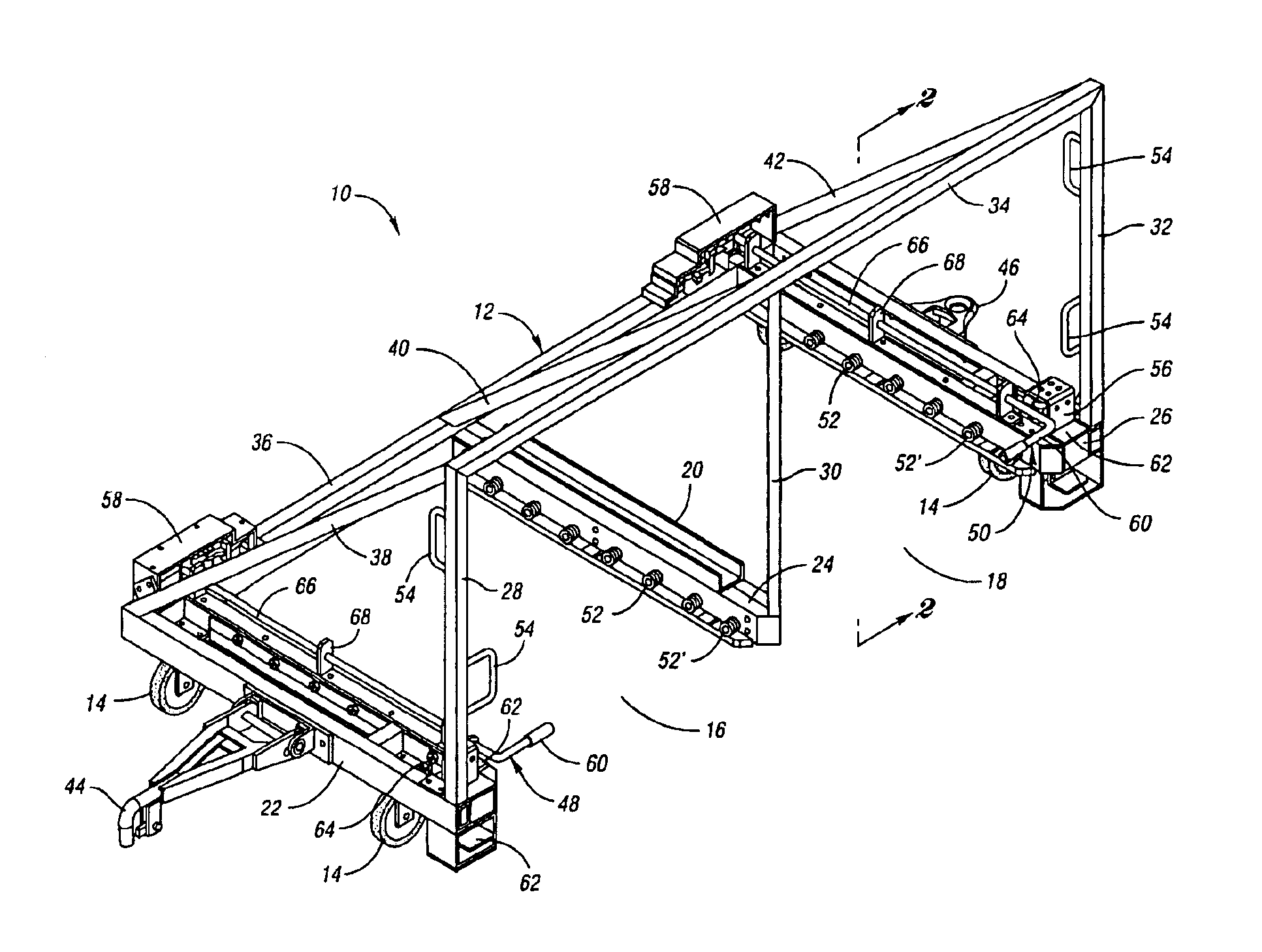
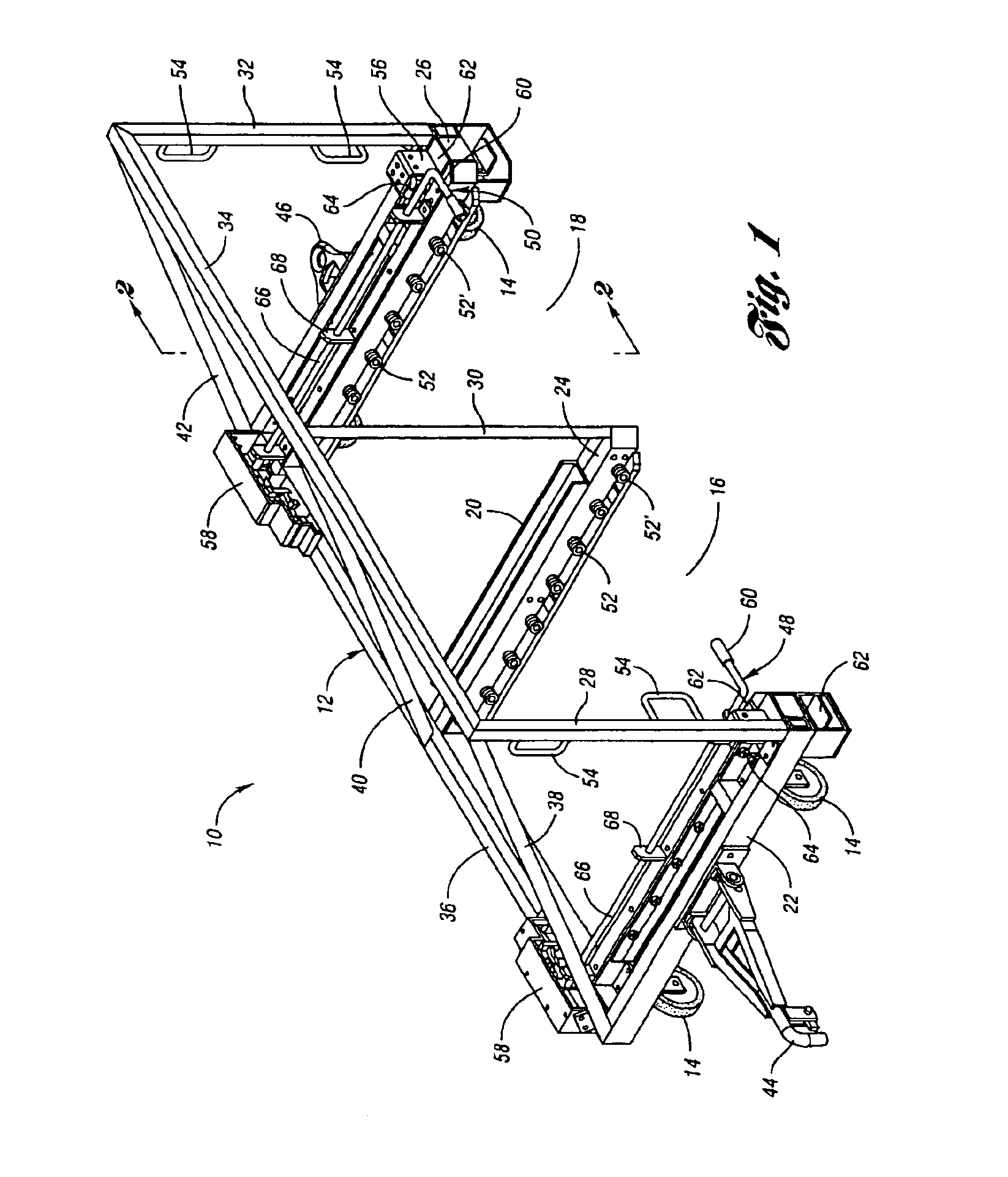
Referring now to FIG. 1, a delivery rack is generally referred to by reference numeral 10. The delivery rack 10 includes a frame generally indicated by reference numeral 12 that is supported on pivotal wheels 14. The frame 12 defines first and second compartments 16 and 18. The frame 12 includes an E-shaped base 20. The E-shaped base includes a front transverse rail 22, a central transverse rail 24, and a back transverse rail 26. The transverse rails are connected on one end to front upright rail 28, central upright rail 30, and back upright rail 32, respectively. The upper ends of the upright rails 26, 28, and 30 are connected to a top rail 34. Side rail 36 is connected by front support rail 38, central support rail 40, and back support rail 42 to the top rail 34. The E-shaped base is formed by the side rail 36 and the transverse rails 22, 24, and 26. First and second compartments 16 and 18 are open at the ends of the transverse rails opposite the side rail 36.

The rack 10 includes ...


PUM

PropertyMeasurementUnit
axis of rotationaaaaaaaaaa
areaaaaaaaaaaa
timeaaaaaaaaaa

Abstract

A component part container delivery rack used in manufacturing operations. An E-frame defining at least two compartments that are open on at least one side that extends between the front and back ends of the rack. The frame is supported on a plurality of wheels and is adapted to receive a dolly in the compartment. Each dolly is removably received in one of the compartments and locked in place when placed in the delivery rack. The locking element includes a pivoting lever that is rotated to lock and unlock the dolly within the compartment. The dolly is supported on roller guide elements that guide the dollies as they are moved into and out of the compartment. The dollies are raised above the floor so that the wheels of the dollies do not contact the floor as it is transported by the rack.

Description

BACKGROUND OF INVENTION1. Field of the InventionThis invention relates to production line stocking equipment.2. Background ArtProduction lines generally, and in particular automotive assembly lines, are serviced by material handling trucks that deliver component parts to production stations. In many instances, a tow motor truck is used to deliver several bins or racks to an unloading area near a production line. At the production line, a lift truck, or hi-low, picks up the bins or racks from the unloading area and delivers them one at a time to the production station. The lift truck sorts the bins and racks that are dropped off by the tow motor as it takes the bins and racks to the proper production line station. Using a forklift truck to move bins and racks normally requires that loads be lifted off the ground and, therefore, may create safety concerns.Tow motors usually take from one to four bins or racks of parts from the storage location to the production line in a train if the ...

Claims


Application Information

Patent Timeline
Patent Type & Authority Patents(United States)
IPC IPC(8): B62B3/04B62B3/10
CPCB62B3/04B62B3/10B62B2501/065B62B2203/74B62B2207/00B62B2202/90
Inventor RIORDAN, ANTHONYGRAHAM, CLIFFLIGGINS, ROBERTCOLBERG, MICHAEL NORBERT
Owner FORD MOTOR CO
Why Eureka
Try Eureka