
Powder coating spray booth with air curtain

a technology of spray booth and powder coating, which is applied in the direction of spray discharge apparatus, electrostatic spray apparatus, domestic heating, etc., can solve the problems of powder overspray still accumulating on the booth walls, affecting the amount of time and effort required to perform color change operations, and the amount of in-process powder is substantially reduced. , the effect of reducing the time and effort required to clean the booth as part of a color change operation

Inactive Publication Date: 2005-03-15
NORDSON CORP
View PDF33 Cites 5 Cited by
  • Summary
  • Abstract
  • Description
  • Claims
  • Application Information

AI Technical Summary

Benefits of technology

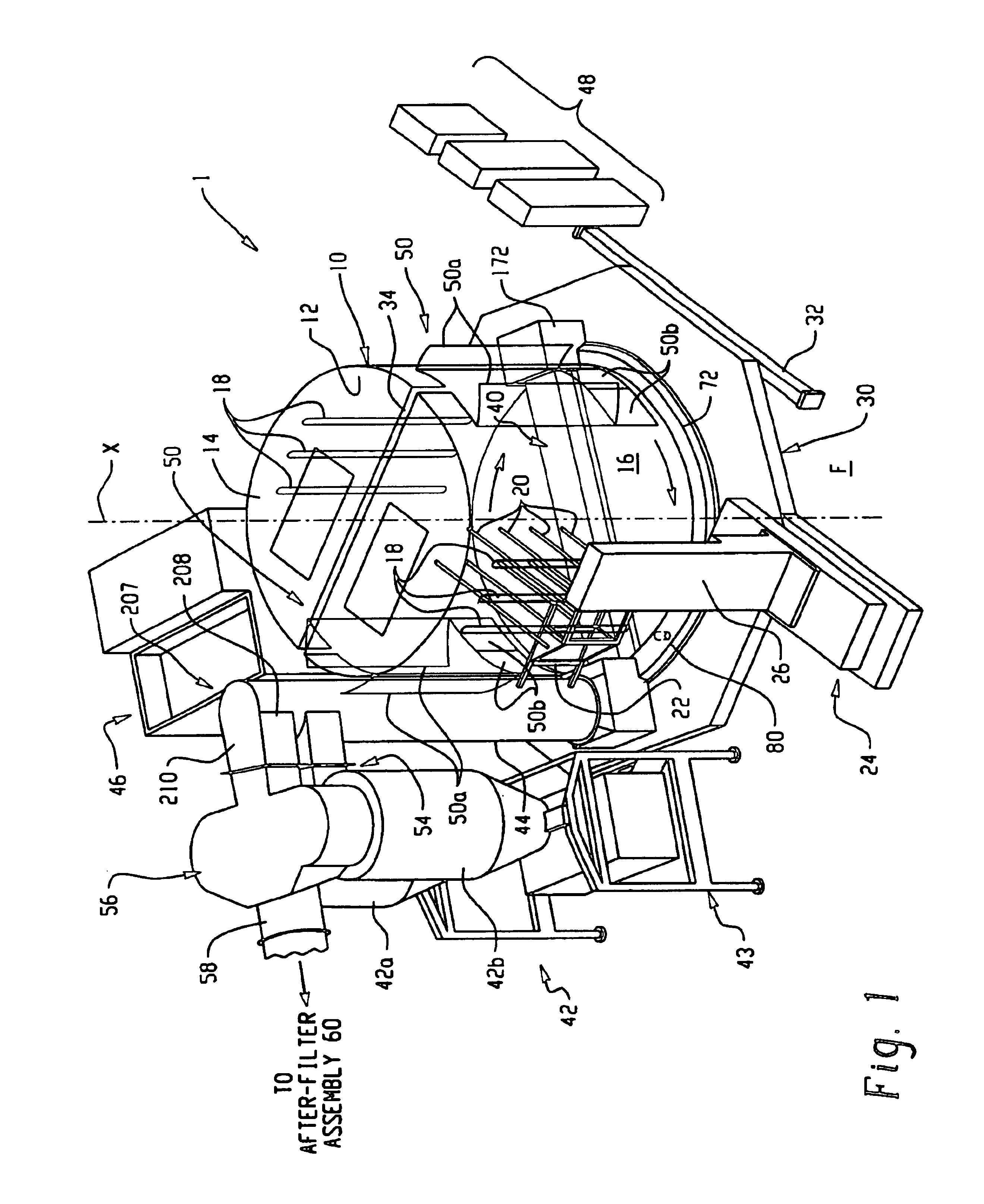
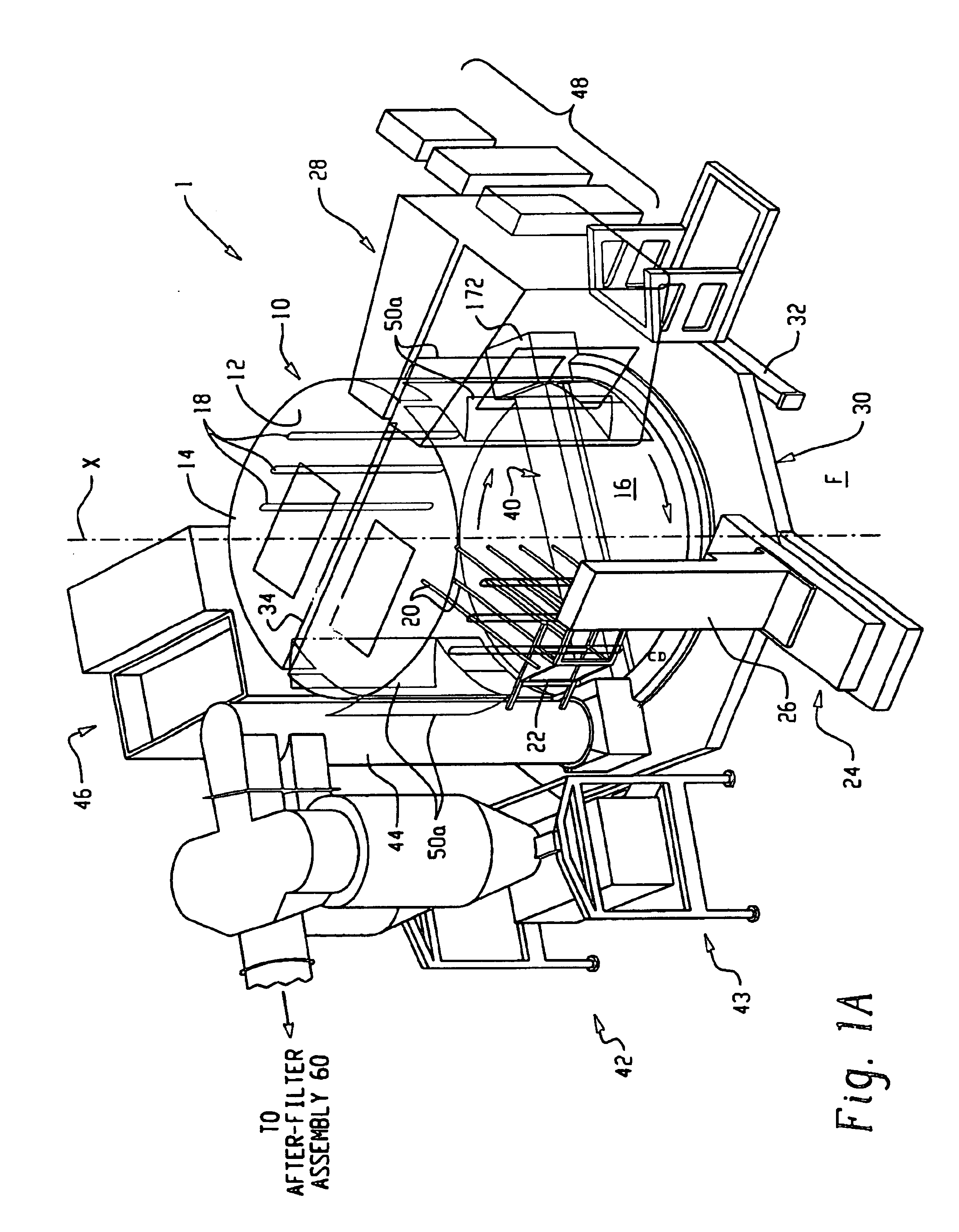
The present invention is directed to improved spray booth designs that are particularly suited for electrostatic spraying operations, although the various aspects of the invention may be incorporated into spray booths that do not utilize electrostatic spraying apparatus. According to one aspect of the invention, a powder extraction system is contemplated in which powder overspray can be continuously extracted from the booth even during a spraying operation. In one embodiment of the invention, a powder spray booth includes a booth canopy wall and ceiling arrangement to contain powder during a spraying operation; and a booth floor that is rotatable relative to the booth wall during a spraying operation. The booth may be generally cylindrical in shape with a round floor. The floor can be rotated about a vertical axis that is also the longitudinal axis of the spray booth. The booth canopy and ceiling are supported on a base frame separately from the floor. By this arrangement, the floor can be rotated relative to the booth canopy. By continuously removing powder overspray in a real-time manner during a powder spraying operation, the amount of in-process powder is substantially reduced and the time and effort required to clean the booth as part of a color changeover is dramatically and significantly reduced.
Still a further aspect of the invention relates to the use of composite materials for the spray booth and floor that are very low in conductivity to minimize powder adhering to the booth and floor, while possessing significant structural properties that enable the configuration to be mechanically sound. In one embodiment, the booth canopy is made of two composite half cylinders that are entirely self-supporting so that the canopy and ceiling can be suspended over an underlying rotatable floor. In this embodiment the floor is also made of very low conductivity composite materials with sufficient structural strength to permit a floor design whereby the floor can be rotated on a central hub.
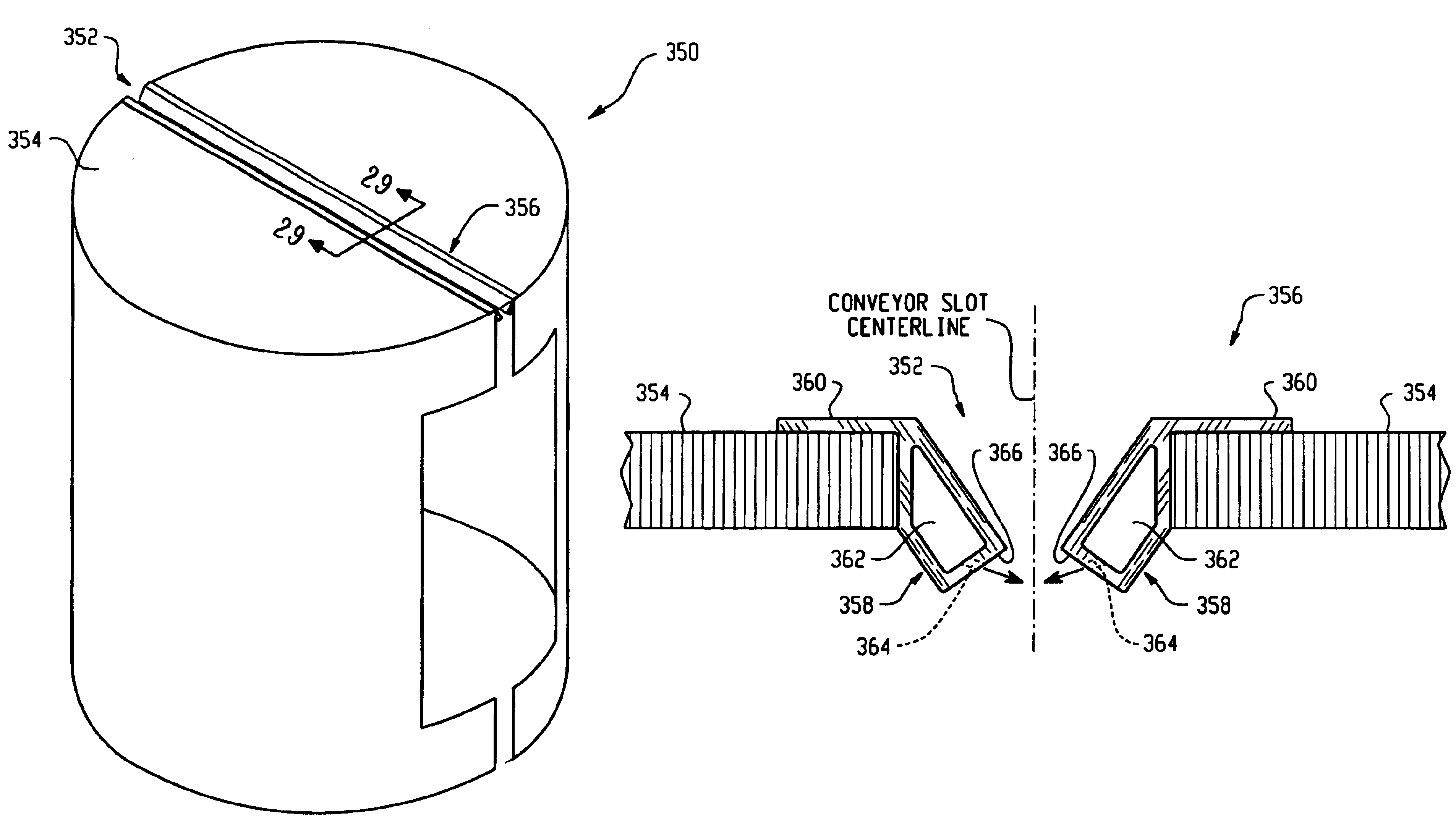
In accordance with another aspect of the invention, powder overspray containment is augmented by eliminating powder escaping through the conveyor slot. In one embodiment, an air curtain is realized in the form of a pair of passageways having air jets formed therein that direct a flow of air into the booth proximate the conveyor slot. In another embodiment, the passageways are used to direct an air stream across a spray booth floor.
A still further aspect of the invention relates to reducing the cost and improving the cleanability of the extraction duct by eliminating a portion of the duct. In one embodiment, a half-duct configuration is utilized in which an extraction duct extends about halfway across the spray booth floor. This also increases the ease of movement within the booth for an operator during a color change or cleaning operation.
In accordance with another aspect of the invention, surface charge on the outside surfaces of the extraction duct are substantially eliminated by disassociating the powder particles from electrostatic charge applied to the powder particles during a spraying operation. In one embodiment, an extraction duct is formed using a non-conductive outer layer and a conductive inner layer.

Problems solved by technology

However, due to the inherent nature of the powder spray pattern, there is a substantial amount of powder that does not adhere to the object and ends up either falling to the floor or collecting on other objects and structures in the immediate area.
However, in known spray booth systems, the powder overspray still tends to collect on the booth walls, ceiling and the booth floor.
Powder overspray presents a two-fold challenge.
Besides the challenge of recovering powder overspray for subsequent use or disposal, powder overspray that collects within the spray booth must be removed from the booth when changing over the powder coating color.
The operation of changing from one color to another is generally known as a “color change” operation and it is an ongoing challenge in the art to make spraying systems that are “quick color change” meaning that the goal is to keep reducing the down time when the spraying system is off line in order to clean the spraying apparatus and system.
Thus, the amount of in-process powder, as well as the amount of powder overspray that remains in the spray booth, have a significant impact on the amount of time and effort it takes to perform a color change operation.
Cleaning a powder coating spray booth can be a labor-intensive effort.
Powder coating materials, in varying degrees, tend to coat all the internal surfaces of the spray booth during a powder coating spray operation, which directly impacts color change time.
Seams between booth panels and recessed ledges, such as where access doors or automatic or manual spray application devices may be located, are typically hard to clean areas and tend to hold concentrations of oversprayed powder coating material that could present a contamination risk after a color change.
These seams require much effort and cost to achieve a virtually uninterrupted, seamless surface.
In addition, known powder coating spray booths have numerous features that reduce operational efficiencies.
In booths using panel members connected with each other and supported by an external frame, numerous seams exist throughout the booth interior that entrap oversprayed powder coating material, thereby making the booth harder to clean during a color change or routine booth maintenance.
Even if otherwise angled or curved toward the floor from the typically vertical side walls, oversprayed powder coating material still tends to accumulate in these areas, thus making them more difficult to clean, as well.
These systems however tend to be cumbersome and are not thorough in the amount of powder removed from the booth.
A substantial effort by one or more operators is still required to completely remove powder from the booth.
Thus there can be a large amount of in-process powder and powder overspray on the booth structure.
Such systems are very complicated mechanically and do not do an adequate job in removing powder from the belt, so much so that in some cases a color change requires a change of the belt itself.

Method used


Image

  • Powder coating spray booth with air curtain
  • Powder coating spray booth with air curtain
  • Powder coating spray booth with air curtain

Examples


Embodiment Construction

With reference to FIGS. 1 and 1A, the present invention is directed to a powder spraying system, as well as specific components within such a system, to improve the cleanability and reduce the time to effect color change operations, while at the same time minimizing impact on transfer efficiency while maximizing impact on containment and recovery of the powder overspray. Various aspects of the invention are described herein in an exemplary manner, and as part of an overall spraying system, but such descriptions are not to be construed in a limiting sense. The various aspects of the invention may be used individually or in any various combinations as required for a particular application. Furthermore, although the present invention is described with respect to the use of electrostatic spray technology, the invention is not limited to the use of electrostatic spraying apparatus.

FIG. 1 illustrates a powder coating spraying system 1 with several of the main components illustrated in a s...


PUM

PropertyMeasurementUnit
angleaaaaaaaaaa
diameteraaaaaaaaaa
diameteraaaaaaaaaa

Abstract

A powder spray booth includes a booth canopy wall arrangement to contain powder during a spraying operation; and a booth floor that is rotatable relative to the booth wall during a spraying operation. The floor can be rotated about an axis that is also the longitudinal axis of the spray booth. The booth may be generally cylindrical in shape with a round floor. The booth canopy and top are supported on a base frame separately from the floor. By this arrangement, the floor can be rotated relative to the booth canopy. A powder extraction apparatus in the form of a low pressure duct suspended off the floor draws up powder that has collected on the floor. The extraction duct is stationary with respect to the rotating floor during a spraying operation. The floor may also be translated along the axis of rotation between a first position in which the floor can rotate and a second position in which the floor is sealed against a lower edge of the booth canopy wall. The booth canopy and floor are made of composite materials that are very low in conductivity to minimize powder adhering to the floor and booth walls. The booth is thus easy to clean with a substantially shorter time period required for color change.

Description

FIELD OF THE INVENTIONThe invention relates generally to powder coating spray systems which use powder containment spray booths. More particularly, the invention relates to a powder spray booth that facilitates cleaning and quick color change by the operation of a rotating floor and a powder overspray extraction duct, which results in very little powder remaining in the spray booth and minimizes the amount of powder in process during a spraying operation.BACKGROUND OF THE INVENTIONPowder coatings are commonly applied to objects by powder spray guns that may be manually operated or automatic. In an automatic system, one or more spray guns are controlled to spray powder onto the objects as the objects are conveyed past the guns. In a manual gun operation, typically the object is suspended or otherwise positioned near a spray gun and the operator controls when the gun starts and stops spraying. A powder spray gun may be selected from a wide variety of gun designs. Since a spraying oper...

Claims


Application Information

Patent Timeline
Patent Type & Authority Patents(United States)
IPC IPC(8): B05B15/12B05B7/14B05B15/04
CPCB05B7/1404B05B15/1211B05B15/1214B05B15/1285B05B15/1222B05B15/1229B05B15/1237B05B15/1218B05B14/41B05B14/45B05B14/48B05B16/25B05B16/40B05B16/405B05B16/60Y02P70/10
Inventor SHUTIC, JEFFREY R.FENIK, LARRYMILLER, SCOTTBARK, BREAN
Owner NORDSON CORP
Learn More