High-precision modeling filament

a high-precision, filament technology, applied in the direction of additive manufacturing processes, manufacturing tools, transportation and packaging, etc., can solve the problems start points and ends, and parts of bead width errors

Inactive Publication Date: 2005-03-15
STRATSYS INC
View PDF13 Cites 73 Cited by
  • Summary
  • Abstract
  • Description
  • Claims
  • Application Information

AI Technical Summary

Benefits of technology

The present invention is high-precision modeling filament for use as feedstock in an extrusion apparatus comprising a liquifier having an inner diameter dL, and a method for forming a three-dimensional object using the modeling filament of the present invention. The liquifier receives the modeling filament and deposits it in molten form in roads having width W and height L. The modeling filament has an average diameter and standard deviation of its diameter which are controlled to meet various criteria of jam resistance, slip resistance, model strength, liquifier overflow prevention and hysteresis-free transient response.
Standard deviation of the diameter (σF) is matched to a filament target diameter. The target filament diameter dT is constrained according to the relationship 0.84 L<dT<dL−6 σF, to meet the jam resistance and slip resistance criteria. The standard deviation is constrained according to the relationship: σF≤2⁢LWSs3⁢π⁢ ⁢dT⁢Δ⁢ ⁢Sg,
to meet the hysteresis-free transient response requirement, where ΔSg is expected average movement of a meniscus within the liquifier, Ss is the maximum allowable gap in a seam, W is road width and L is road height. The standard deviation is further constrained to meet model strength and liquifier overflow prevention criteria, although these criteria may be redundant to the hysteresis-free transient response requirement.
The filament is manufactured so that the average filament diameter <dF> equals the target diameter. A particular filament manufactured in accordance with the teachings of the present invention, suitable for use in a 0.076 inch inner diameter liquifier, has a target diameter between 0.069 and 0.073 inches and a standard deviation of less than or equal to 0.0004 inches. The modeling filament of the present invention is used to form high-quality models.

Problems solved by technology

In the modeling systems of the current art, bead width errors arise, particularly at start points and end points of the tool path, for instance, at the location of a “seam” (i.e., the start and end point of a closed-loop tool path).
Bead width errors arise in part due to inconsistent flow rates.
These errors cause undesired inconsistencies in the shape of the resulting model.
While this technique does reduce errors, its has disadvantages in that each modeling machine must be equipped with a sensor, adding to the cost and maintenance of the machines.
Also, using this technique, some errors have been observed to remain.

Method used


Image

  • High-precision modeling filament
  • High-precision modeling filament
  • High-precision modeling filament

Examples


Embodiment Construction

The objects of the invention are to produce modeling filament having a diameter that meets tolerance limits established according to certain identified criteria, and to produce high-quality models using the modeling filament as feedstock. The present invention is based on the recognition that variances in filament diameter, as found in the prior art, can significantly degrade the performance of a fused deposition modeling liquifier resulting in a poor quality model. We will describe the tolerance limits of the present invention and a manufacturing process incorporating filament diameter control that will produce modeling filament that meets these limits.

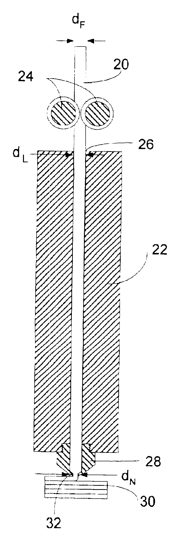
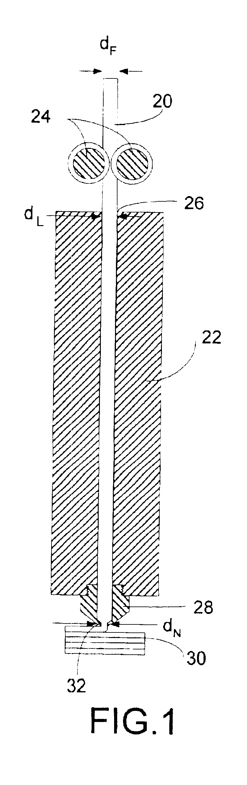
FIG. 1 shows a cross-section of an exemplary liquifier 22, combined with a pair of feed rollers 24 that impel a strand of filament 20 into the inlet or cap 26 of the liquifier 22. The feed rollers 24 are driven at a controlled rate by a motor (not shown). A nozzle or tip 28 selectively deposits flowable thermoplastic onto a model 30 ...


PUM

PropertyMeasurementUnit
diameteraaaaaaaaaa
lengthaaaaaaaaaa
inner diameter dLaaaaaaaaaa

Abstract

Disclosed is a modeling filament for use as feedstock in a fused deposition modeling liquifier, and a method for manufacturing the filament. The diameter and standard deviation of the filament are controlled to meet various tolerance requirements of jam resistance, slip resistance, model strength, liquifier overflow prevention and hysteresis-free transient response. Standard deviation of the filament diameter is matched to a filament target diameter. The resulting filament is used to form high-quality models.

Description

BACKGROUND OF THE INVENTIONThe present invention relates generally to the fabrication of three-dimensional objects using extrusion-based layered manufacturing techniques. Specifically, it relates to modeling filament used as a feedstock in a fused deposition three-dimensional modeling machine.Three-dimensional models are used for functions including aesthetic judgments, proofing a mathematical model, forming hard tooling, studying interference and space allocation, and testing functionality. Extrusion-based layered manufacturing machines build up three-dimensional models by extruding solidifiable modeling material from a nozzle tip carried by an extrusion head onto a base. The modeling material flows when heated, solidifies upon a drop in temperature, and adheres to the previous layer with an adequate bond upon solidification. Suitable materials include waxes, thermoplastic resins, and various metals. Movement of the extrusion head with respect to the base is performed in a predeter...

Claims


Application Information

Patent Timeline
Patent Type & Authority Patents(United States)
IPC IPC(8): B29C67/00B29C48/92B29C48/05B29C48/625B29K105/08D01F6/00D02J1/22
CPCB29C67/0055B29C67/0085B29C47/92Y10T428/2913Y10T428/298B29C48/92B29C2948/92409B29C48/05B29C48/625B29C2948/92123B29C2948/92523B29C2948/92571B29C2948/9259B29C2948/92619B29C2948/92904B29C2948/92933B29C2948/92952B33Y70/00B33Y80/00B29C64/118B29C64/106
Inventor COMB, JAMES W.PRIEDEMAN, JR., WILLIAM R.LEAVITT, PAUL J.SKUBIC, ROBERT L.BATCHELDER, JOHN SAMUEL
Owner STRATSYS INC
Why Eureka
Try Eureka