Slip resistant mat and process of manufacture of same

Inactive Publication Date: 2005-03-15
CINTAS CORP SERVICES INC
View PDF30 Cites 8 Cited by
  • Summary
  • Abstract
  • Description
  • Claims
  • Application Information

AI Technical Summary

Benefits of technology

One advantage of the present invention is that the mat resists slipping to a much greater extent than existing mat designs. Another advantage of the invention is that the edges of the mat are more stable and therefore it is less of a tripping hazard or obstacle than traditional mats in which the edge easily rolls up onto the mat. Another advantage is that it provides the slip-resistance features without adding any weight or installation complexity to existing mat designs. Another advantage is that the invention does not require any permanent fastening means and is therefore easy to move to different locations. Another advantage is that the recessions provide some additional cushioning effect for pedestrian and vehicular traffic. Another advantage is that the recessions' cushioning effect has an anti-fatigue effect, thereby resulting in reduced wear and tear and routine maintenance. Another advantage of the invention is that the slip-resistance is effective on a wide variety of surfaces because of the variable sized and spaced recessions.

Problems solved by technology

However, both of these approaches resulted in floor mats that were not skid resistant on smooth floors, especially those floors with high traffic areas or loads being moved over them.
For the smooth back mats, movement of the mat results from similar forces and the lack of any device intended to secure the mat in place.
While this approach is well-developed, it results in floor mats that are difficult or impossible to move from place to place and the structures required to attach the mat add a measure of expense to the mat and difficulty to the installation.
If the frame is fastened or embedded, then the problems mentioned above remain.
While this invention provides acceptable slip-resistance for light shower and bath mat applications, traditional suctions cups are not sufficient to prevent slipping in high traffic areas and also result in waves forming within mats, which results in movement of the mats and a less stable and flat top surface for the mats.
As mentioned, existing approaches to reducing movement of mats include significant limitations.
Further, the known approaches require additional space, components, installation effort and expense.

Method used


Image

  • Slip resistant mat and process of manufacture of same
  • Slip resistant mat and process of manufacture of same
  • Slip resistant mat and process of manufacture of same

Examples


Embodiment Construction

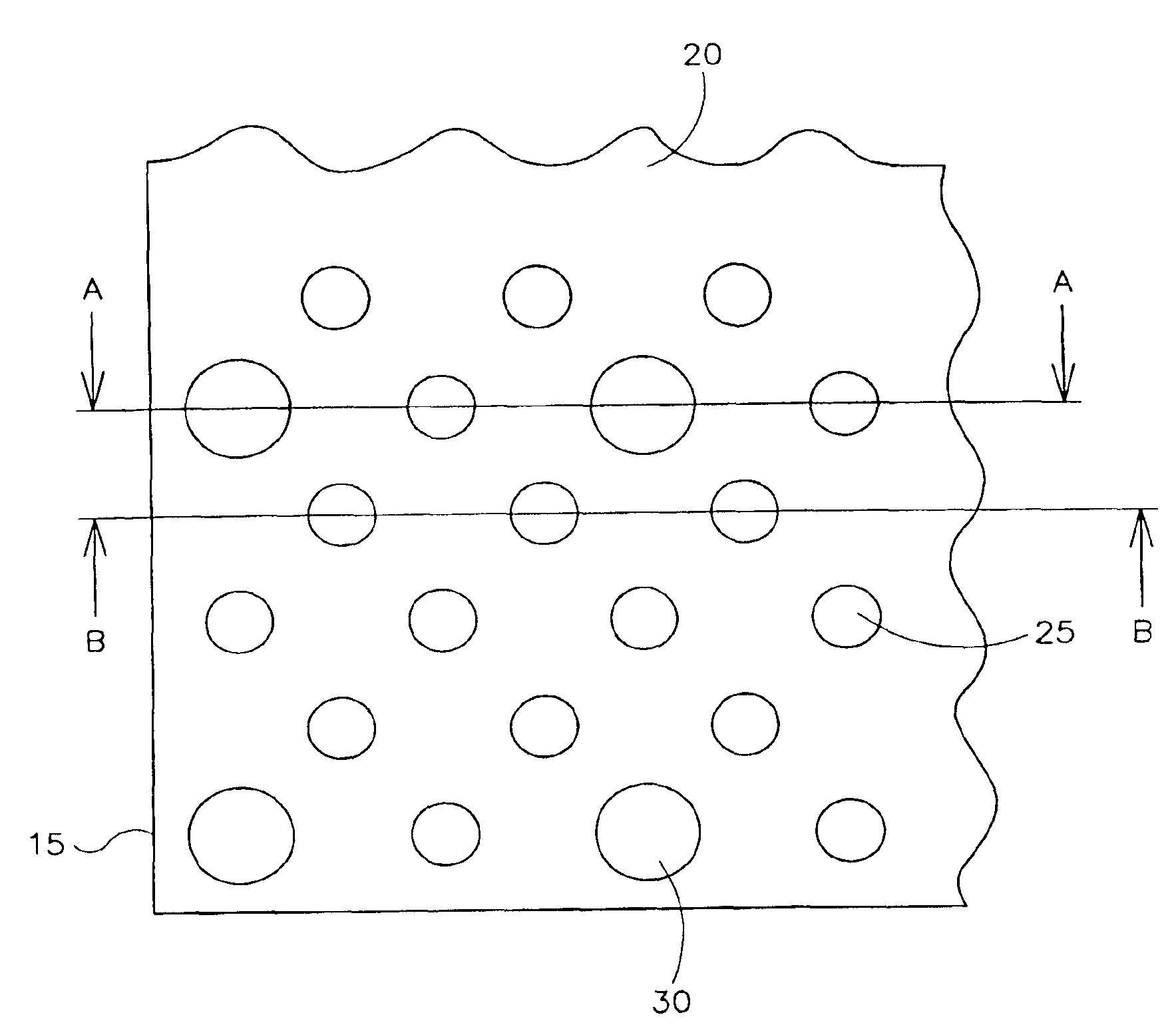
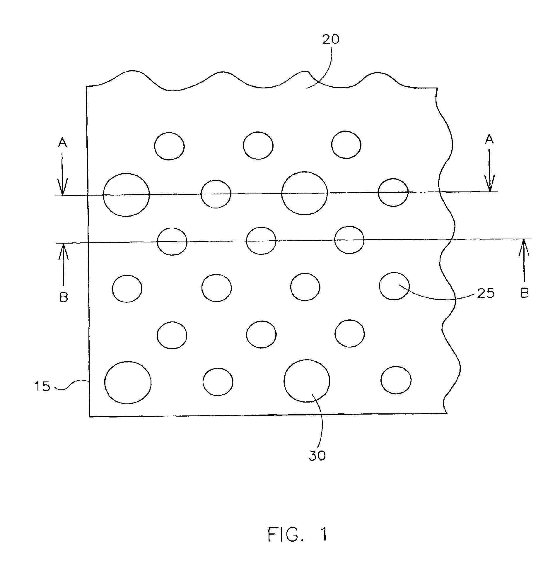
FIG. 1 illustrates a portion of a mat (20) with a plurality of small recessions (25) and large recessions (30) that extend nearly to the edge of the mat (15).

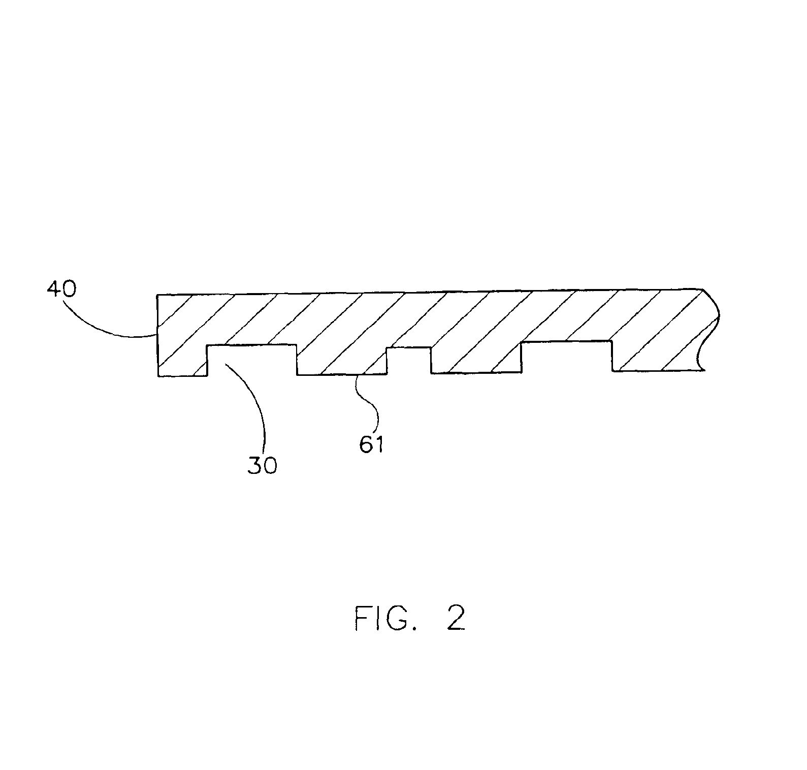
FIG. 2 illustrates a view of a cross-section of a single layer mat (20). The mat (20) has a single layer (40) which contains recessions (30) in the underside (61) of the bottom layer (40).

FIG. 3 illustrates a view of a cross-section of another single layer mat (20). The mat (20) has a single bottom layer (40) which contains recessions (30) in the underside (61) of the bottom layer (40). The bottom layer has a yarn, carpet or other fabric layer (52) laminated or otherwise bonded to the upper surface (60) of the bottom layer (40).

FIG. 4 illustrates a view of a cross-section of a multi-layer laminated mat (20) comprised of a bottom layer (40) and an upper layer (50). The upper surface (60) of the bottom layer (40) is laminated to or otherwise bonded with the lower surface (70) of the support layer (51) of the upper layer (50). The...


PUM

PropertyMeasurementUnit
Lengthaaaaaaaaaa
Lengthaaaaaaaaaa
Lengthaaaaaaaaaa

Abstract

A slip resistant floor mat composed of one or more layers of material the bottom layer of which incorporates a plurality of recessions in the bottom surface of the bottom layer that comes into intended surface, such as a floor. The mat may be manufactured by using a press mold to form recessions on the bottom surface of the bottom layer of the mat, and if desired, additional layers may be laminated together with the bottom layer.

Description

FIELD OF INVENTIONThis invention relates generally to slip resistant, anti-skid or anti-creep mats.BACKGROUND OF THE INVENTIONIn the past, dust floor mats, consisting of rubber backed carpet tuft, were made with either a smooth back, primarily for solid or non carpeted floors, or with a variety of “grippers” or “cleats” arranged to reduce the movement on carpeted floors. However, both of these approaches resulted in floor mats that were not skid resistant on smooth floors, especially those floors with high traffic areas or loads being moved over them. The movement of in the gripper / cleat mat design results from the force of foot and vehicle traffic on the mat which causes deformation around the compressed area and upon removal of such force the mat returns to a different position. For the smooth back mats, movement of the mat results from similar forces and the lack of any device intended to secure the mat in place.A number of approaches have been taken to attempt to reduce the move...

Claims


Application Information

Patent Timeline
IPC IPC(8): A47G27/04A47G27/00A47L23/26A47L23/00B32B5/02B32B3/30B32B5/00
CPCA47G27/0412A47L23/266B32B3/30B32B5/02B32B5/00Y10T428/24983Y10T428/24612Y10T428/24942Y10T428/23979
Inventor MALPASS, IAN S.COFER, JEFFREY L.
Owner CINTAS CORP SERVICES INC
Why Eureka
Try Eureka