Thermal processing apparatus

a technology of thermal processing and substrate, applied in the field of thermal processing apparatus, can solve the problems of irregular temperature, relatively slow increase of temperature on the outer surface, and irregular temperature, and achieve the effects of reducing displacement, improving temperature uniformity of substrate heating, and suppressing overlap

Inactive Publication Date: 2005-03-15
DAINIPPON SCREEN MTG CO LTD
View PDF4 Cites 12 Cited by
  • Summary
  • Abstract
  • Description
  • Claims
  • Application Information

AI Technical Summary

Benefits of technology

The present invention is intended for a technique for reducing displacement between a substrate and an auxiliary ring thereby suppressing overlaps and rendering the overlaps constant for improving temperature uniformity of the substrate in heating.
Thus, the thermal processing apparatus can correctly position the substrate in response to the ring. When placing the substrate on the ring, the thermal processing apparatus can render overlaps small and constant, for improving temperature uniformity of the substrate in thermal processing.
Thus, a clearance between the first and second surfaces is reduced due to contraction of the ring member or the support member in temperature reduction, whereby the thermal processing apparatus can limit displacement of the ring member.
Thus, the thermal processing apparatus can block light directed downward below the substrate and improve temperature uniformity of the substrate in heating.
Thus, the thermal processing apparatus employing the lamp can improve temperature uniformity of the heated substrate.
Accordingly, an object of the present invention is to improve uniformity of a substrate temperature in processing of irradiating the substrate with light from a lamp for heating the substrate.

Problems solved by technology

If the substrate and the auxiliary ring largely overlap with each other, however, the thermal capacity of the outer edge of the substrate (apparent thermal capacity in consideration of influence by the thermal capacity of the auxiliary ring) is increased in heating, to result in temperature irregularity (such ununiformity that the temperature of the outer edge is relatively reduced in heating and relatively increased in cooling) allowing no compensation through adjustment of the lamp output between a portion around the center of the substrate and the outer edge thereof.
Also when the centers of the substrate and the auxiliary ring deviate from each other, the overlaps get inconstant on the outer edge of the substrate, and hence the thermal capacity gets ununiform on the outer edge of the substrate, leading to temperature irregularity.
When the auxiliary ring and the screening ring largely overlap with each other, there is such a possibility that the temperature is relatively slowly increased on the outer edge of the auxiliary ring when heating the substrate, to crack the auxiliary ring due to excess stress resulting from temperature difference between the outer edge and the inner periphery.
Consequently, it is difficult to suppress dispersion of the thickness in formation of an oxide film or the like, for example, within a range more strictly required in the future.

Method used


Image

  • Thermal processing apparatus
  • Thermal processing apparatus
  • Thermal processing apparatus

Examples


Embodiment Construction

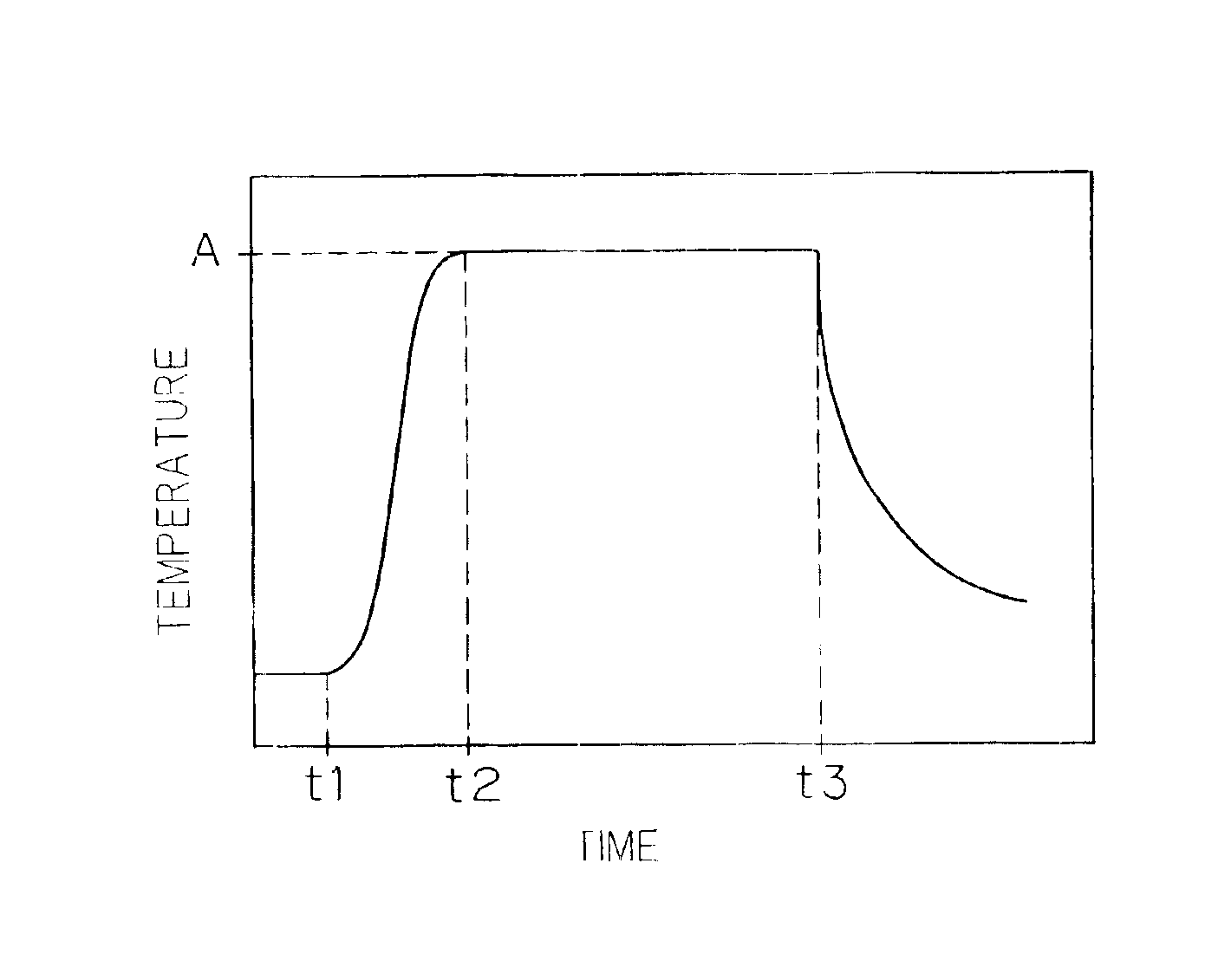
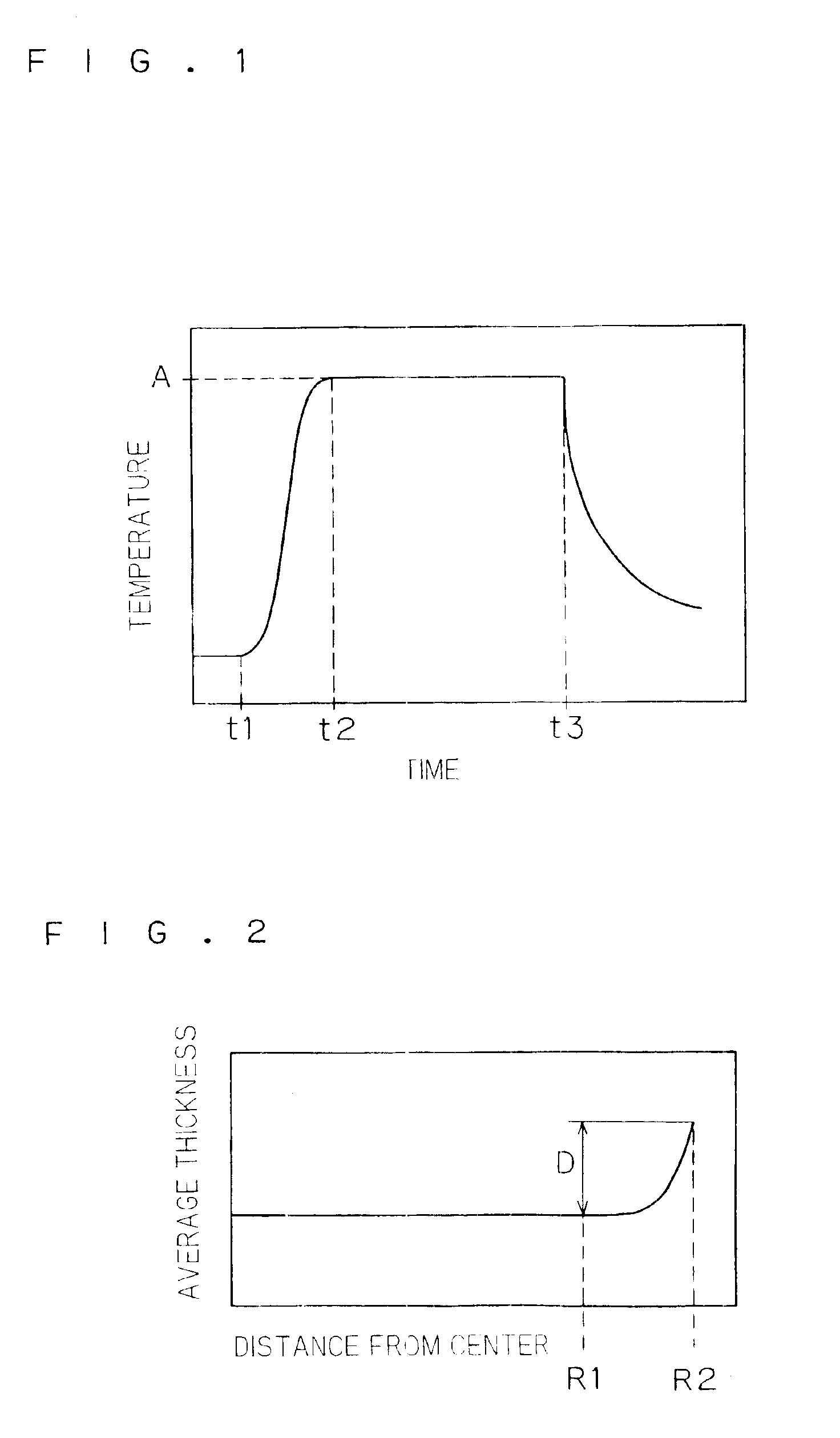
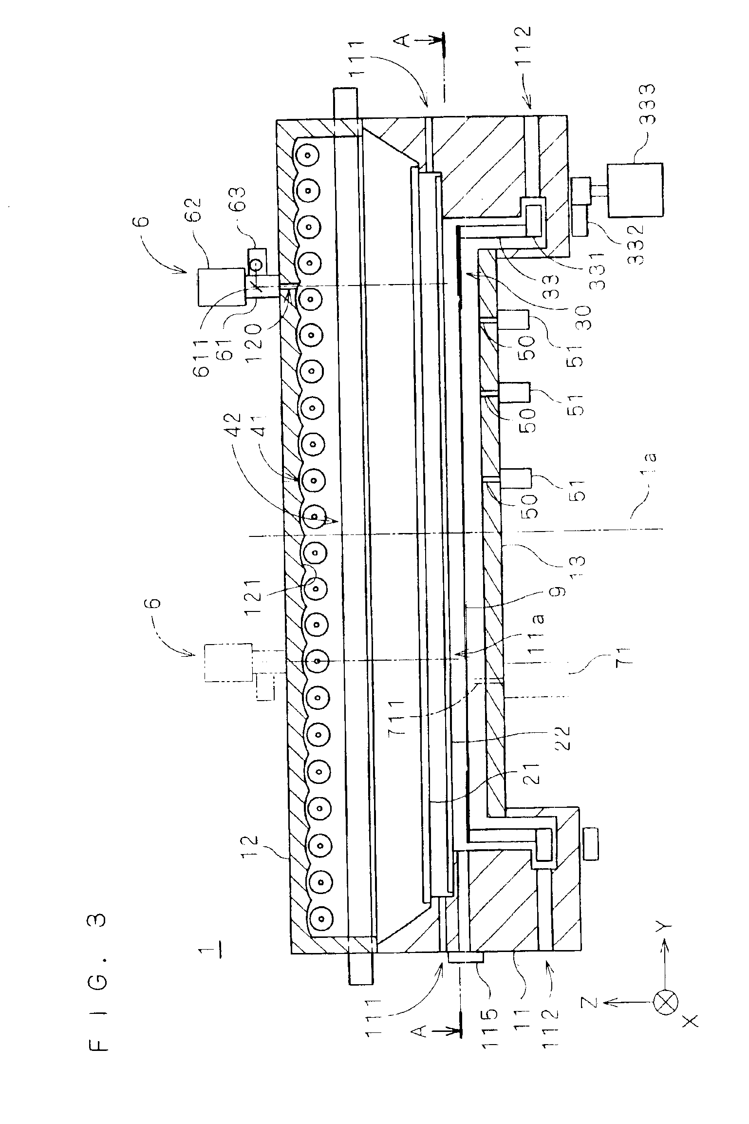
FIG. 3 is a longitudinal sectional view showing the structure of a thermal processing apparatus 1 according to a first preferred embodiment of the present invention. FIG. 3 omits parallel oblique lines with respect to sections of details.

The thermal processing apparatus 1 irradiates a substrate 9 with light in a prescribed atmosphere thereby performing various thermal processing (oxidization, annealing, CVD etc.) accompanied by heating. In the thermal processing apparatus 1, a body part 11 forming the apparatus body, a lid part 12 covering the upper portion of the body part 11 and a reflector 13 arranged on the central bottom surface of the body part 11 form a chamber. A chamber window 21 of quartz vertically partitions the internal space of the chamber, and a support ring group 30 supports the substrate 9 in a lower processing space 11a. An O-ring (not shown) seals the clearance between the chamber window 21 and the body part 11, which has a cylindrical inner side surface.

A plurali...


PUM


Abstract

In a thermal processing apparatus irradiating a substrate with light from a lamp for heating the substrate, an opening is formed in a reflector for mounting a camera unit. The camera unit images three portions of an auxiliary ring supporting the substrate, for obtaining the position of the center of the auxiliary ring before the thermal processing apparatus receives the substrate therein. The camera unit further images the substrate for obtaining the position of the center of the substrate before the thermal processing apparatus receives the substrate therein and places the same on the auxiliary ring. The thermal processing apparatus moves the substrate so that the center thereof coincides with the center of the auxiliary ring, and thereafter places the former on the latter. Thus, the auxiliary ring can be so designed as to reduce overlaps of the auxiliary ring and the outer edge of the substrate while the overlaps can be rendered uniform over the entire circumference of the substrate for improving temperature uniformity of the substrate.

Description

BACKGROUND OF THE INVENTION1. Field of the InventionThe present invention relates to a technique of heating a substrate with light.2. Description of the Background ArtAs the requirement for refinement of a device such as a semiconductor device is increased, a rapid thermal process (hereinafter abbreviated as “RTP”) has been going to play an important role as one of heating steps for a semiconductor substrate (hereinafter referred to as “substrate”). The RTP is performed mainly with a lamp employed as a heat source. Briefly stated, a processing chamber is kept in a prescribed gas atmosphere for heating a substrate to a prescribed temperature (e.g., 1100° C.) in several minutes (temperature increase step), maintaining the substrate at the temperature for a constant time (e.g., several 10 seconds) (holding step) and thereafter turning off the lamp thereby rapidly cooling the substrate.The RTP is employed for performing processing such as that of preventing an impurity from thermal re-d...

Claims


Application Information

Patent Timeline
Patent Type & Authority Patents(United States)
IPC IPC(8): H01L21/00H01L21/68H01L21/02H01L21/67H01L21/324
CPCH01L21/324H01L21/681H01L21/67115
Inventor KOBAYASHI, TOSHIYUKIKOYAMA, YOSHIHIROTAKAHASHI, MITSUKAZU
Owner DAINIPPON SCREEN MTG CO LTD
Why Eureka
Try Eureka