Method for improving the control of power plants when using input/loss performance monitoring

a technology of power plant and performance monitoring, applied in the direction of instruments, nuclear elements, lighting and heating apparatus, etc., can solve the problems of affecting the stability of the control of fossil-fired thermal systems, the loss of all useful output, and the possibility of dangerous results for equipment and personnel, so as to improve the stability of dcs, improve the consistency of base signals, and improve the control of such fossil-fired thermal systems

Inactive Publication Date: 2005-03-15
EXERGETIC SYST
View PDF6 Cites 29 Cited by
  • Summary
  • Abstract
  • Description
  • Claims
  • Application Information

AI Technical Summary

Benefits of technology

This invention relates to a fossil-fired thermal system such as a power plant or steam generator, and, more particularly, to a method to improve the control of such fossil-fired thermal systems. This invention employs computational outputs produced from any of the Input / Loss methods, as direct input to Distributed Control Systems used by fossil-fired thermal systems such that improvements to the consistency of base signals employed by the DCS and improvements in DCS stability when transitioning between operational modes may be achieved. The use of such values internal to the DCS is not altered by this invention, however the supply of such values as taught herein is unique.

Problems solved by technology

For example, if the system indication of fuel flow is inconsistent, producing discontinuities in the signal and / or producing opposing trends versus the actual, unstable operations with dangerous results to equipment and personnel may be expected.
In cases when any instability exceeds design limits, the system will trip off-line, causing loss of all useful output.
If the system is tripped from a high load, this most likely will cause considerable stress on materials and shorten fatigue life of equipment.
Use of an on-line instrument analyzer may have functionality in supplying the Btu-Compensator, but in general these instruments are not reliable and thus have not received acceptance by the power industry.

Method used


Image

  • Method for improving the control of power plants when using input/loss performance monitoring
  • Method for improving the control of power plants when using input/loss performance monitoring
  • Method for improving the control of power plants when using input/loss performance monitoring

Examples


Embodiment Construction

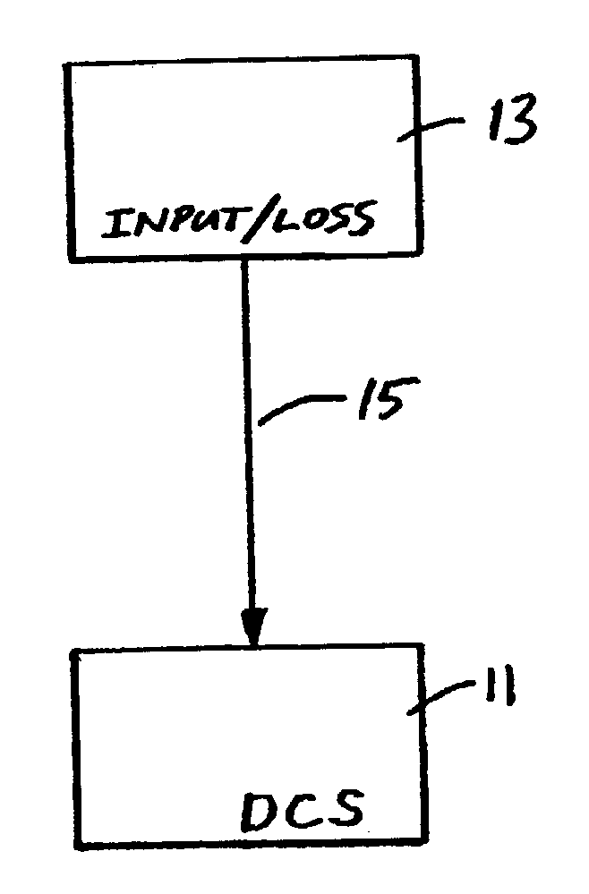
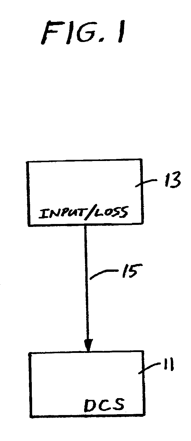
To assure an appropriate teaching of this invention, its description is divided by sub-sections. The first presents nomenclature, definitions of equation terms, typical units of measure, and meaning of terms used herein (such as Choice Operating Parameters and System Effect Parameters). The next sub-sections teach specific methods. The use and understanding of multidimensional minimization techniques, leading to correction factors applied to Choice Operating Parameters which in turn are required by any of the Input / Loss methods, is fully taught in '877. Although the details of computations leading to a Btu-Compensator, fuel flow and other values employed by the DCS as taught by this invention are explained herein, they are fiber explained in '994 and '429 and related provisional patent applications and Continuation-In-Parts.

Definitions of Equation Terms with Typical Units of Measure

Stoichiometric Terms:a=Moles of combustion O2 input to the system; moles / base.aβ=Moles of O2 entering ...


PUM


Abstract

This invention relates to a fossil-fired thermal system such as a power plant or steam generator, and, more particularly, to a method for improving the control of a power plant or steam generator through use of computed output obtained from any of the Input/Loss methods. Typically such computed output may consist of As-Fired fuel flow, fuel heating value, fuel Firing Correction, and other similar terms which might effect the operating control system of a power plant or steam generator.

Description

This invention relates to a fossil-fired thermal system such as a power plant or steam generator, and, more particularly, to a method for improving the control of a power plant or steam generator through use of computed output obtained from any of the Input / Loss methods. Typically such computed output may consist of As-Fired fuel flow, fuel heating value, fuel Firing Correction, Energy Released from Combustion, and other similar terms which might effect the operating control system of a power plant or steam generator.BACKGROUND OF THE INVENTIONAlthough especially applicable to “The Input / Loss Method” as installed at coal-fired power plants, this invention may be applied to any on-line monitoring method and any other of the “Input / Loss methods”, installed at any thermal system burning a fossil fuel. Such monitoring is assumed to be conducted in a continuous manner (i.e., on-line), processing one monitoring cycle after another, each cycle includes determining stoichiometric balances o...

Claims


Application Information

Patent Timeline
Patent Type & Authority Patents(United States)
IPC IPC(8): F22B35/00F22B35/18F23N5/00F23N1/00G05B13/04G05B23/02
CPCF22B35/18F23N1/002F23N5/003G05B13/042F23N2021/10F23N2023/40F23N2025/22F23N2021/08F23N2223/40F23N2221/08F23N2225/22F23N2221/10
Inventor LANG, FRED D
Owner EXERGETIC SYST
Why Eureka
Try Eureka