Method and apparatus to measure blood flow by an introduced volume change

Inactive Publication Date: 2005-03-22
TRANSONIC SYST
View PDF51 Cites 59 Cited by
  • Summary
  • Abstract
  • Description
  • Claims
  • Application Information

AI Technical Summary

Benefits of technology

The volume change method employs, in some of its embodiments, changes in indicator concentration as a means to assess relative changes in local flow in a conduit. These methods bear some similarity to the conventional indicator dilution family of methods, often called Stewart-Hamilton and Fick principle methods. Indicator dilution methods use indicator concentration as the primary means to assess blood flow, according to a simple principle: if one introduces a known amount of indicator in a flow and monitors downstream the resulting absolute concentration of that indicator, one can deduce the volume rate of flow. Indicators are used differently in

Problems solved by technology

While prior methods have practical uses during specific medical studies and protocols, no method has been developed that has found widespread use during vasc

Method used


Image

  • Method and apparatus to measure blood flow by an introduced volume change
  • Method and apparatus to measure blood flow by an introduced volume change
  • Method and apparatus to measure blood flow by an introduced volume change

Examples


embodiment 1 (

Two Sensor Catheter to Measure Velocity with Single Injection)

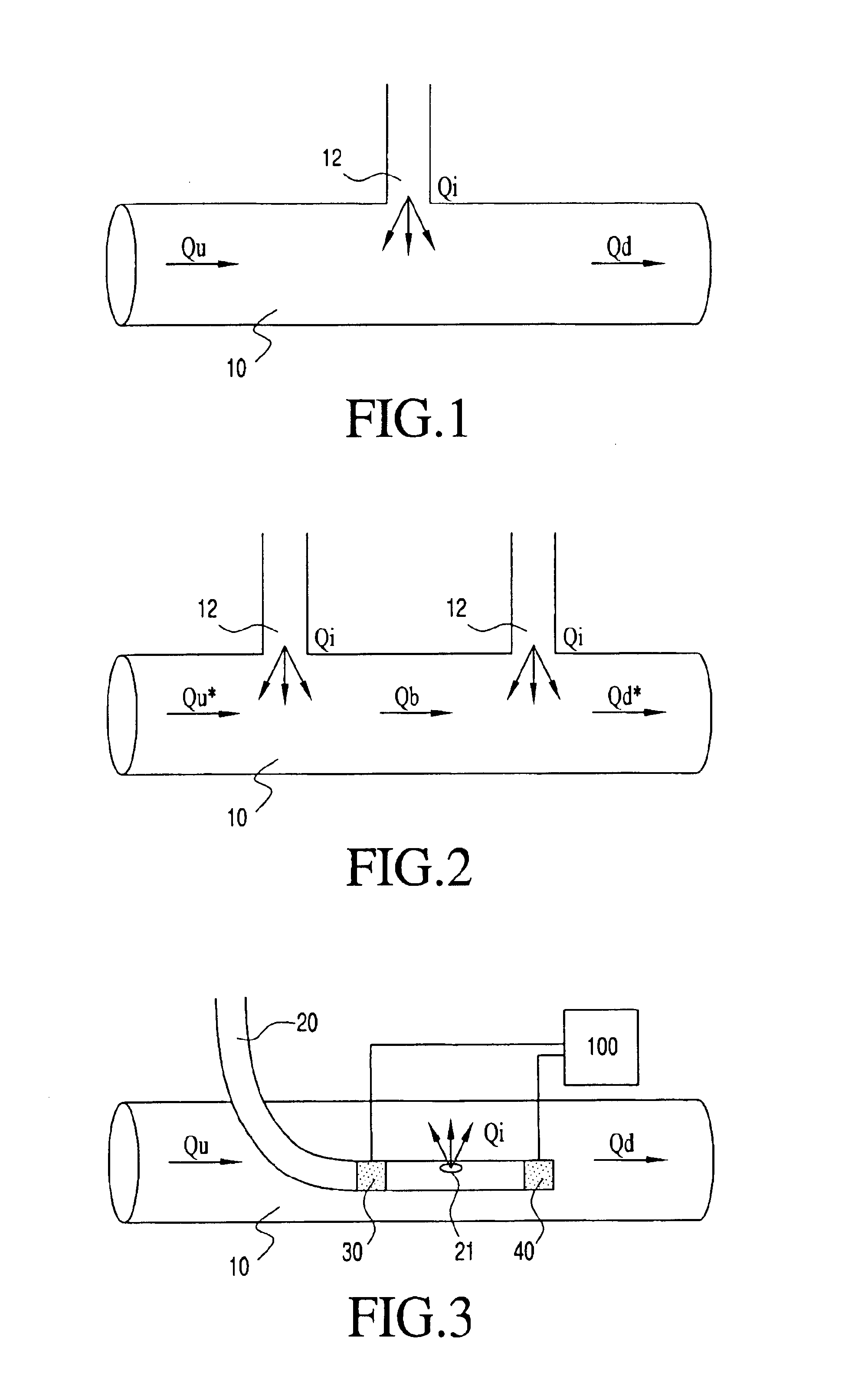
As shown in FIG. 3, in the first embodiment, the catheter 20 with two sensors 30, 40 is employed to measure a velocity of blood (such as in m / sec) using a single volume change introduction through the port 21. The sensors 30, 40 may be any type of sensor as previously disclosed. In a preferred construction, the sensors 30, 40 are connected to the catheter 20 to be located within the conduit 10.

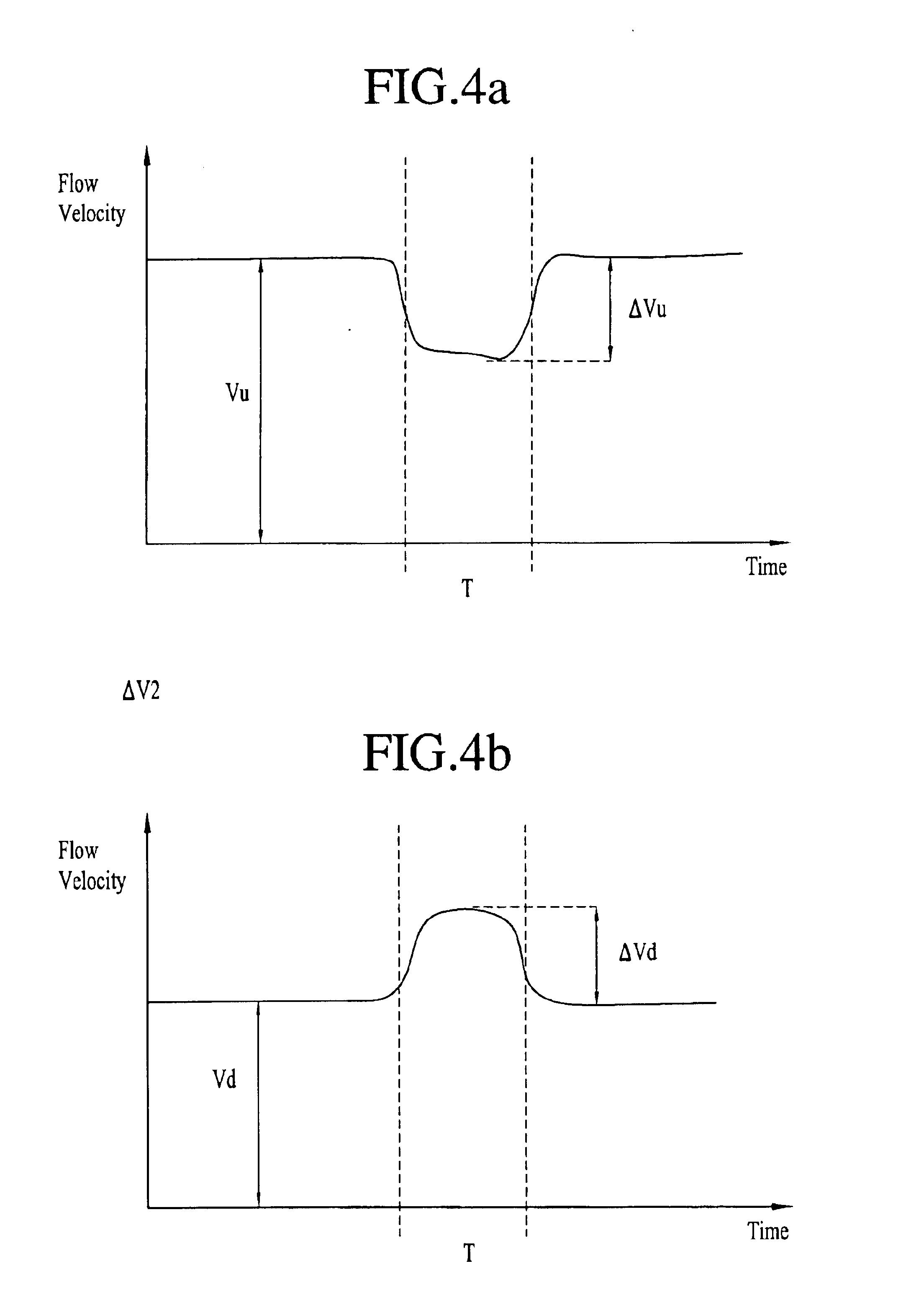
The catheter 20 is inserted into the conduit 10 as shown in FIG. 3. The two sensors 30, 40 measure blood velocity, or a parameter that corresponds to flow velocity at their respective locations in the conduit 10. The first sensor 30 measures a parameter Vu, the second sensor 40 measures a parameter Vd, each corresponding to flow velocity at its local respective site. Because flow velocity corresponds to volume flow, an equation analogous to Eq. 5 is: Q=Qi(Δ⁢ ⁢VdVd-Δ⁢ ⁢VuVu)(Eq. ⁢20)where ΔVu and ΔVd are changes corresponding to upst...

embodiment 2 (

Velocity Sensors Outside the Vessel with Single Injection)

Referring to FIG. 5, in the second embodiment, flow (blood) velocity sensors 30, 40 are located outside the conduit 10 and a single volume change introduction is made through port 21 in the catheter 20 which is located in the conduit. This embodiment is analogous to Embodiment 1 (Eq. 5 and Eq. 20) but sensors 30, 40 are located outside of the conduit 10. Also shown in FIG. 5 are alternative locations for sensors 30′, 40′ on the skin of the patient, or 30″,40″ spaced from the patient.

Referring to FIG. 6, the upstream sensor 30 and the downstream sensor 40 may be adjacent each other and generally aligned along the relevant flow at the injection site 21, wherein each sensor defines a sensing zone such that an upstream sensor 30 sensing zone 33 extends upstream of the injection site and a downstream sensor 40 sensing zone 43 extends downstream of the injection site. In a further configuration shown in FIG. 7, a single sensor 35 m...

embodiment 3

d Velocity Sensor Catheter with Two Injections)

As shown in FIG. 8, the third embodiment employs the catheter 22 having a single flow sensor 50, such as a blood velocity sensor, located intermediate two volume change site ports, an upstream port 51 and a downstream port 53, through which introductions are made into the flow in the conduit 10 through the catheter.

The catheter 22 is inserted into the conduit 10 (FIG. 8). In this embodiment, flow may be measured by making two volume change introductions. One volume change is made upstream through the upstream port 51, the other volume change is made downstream of the single sensor 50 (blood velocity sensor) through the downstream port 53. The equation is analogous to Eq. 19. Q=Qi[Δ⁢ ⁢VdV-Δ⁢ ⁢VuV)(Eq. ⁢21)

In this equation, V is blood velocity at the location of the single sensor 50; ΔVd and ΔVu the changes in blood velocity from a volume change introduction downstream of the sensor and upstream of the sensor respectively. (FIG. 9).

The in...


PUM


Abstract

A method and apparatus for determining an initial flow rate in a conduit is disclosed. A known change is made to the flow to be measured, resulting changes (or values corresponding to these changes), or relative changes in the flow to be measured are monitored and the initial flow in the conduit is calculated from the value of the known change and monitored changes. Devices to practice the method include catheters having one or two sensors and one or two sites for introducing the volume change.

Description

FIELD OF THE INVENTIONThe present invention relates to flow measurements, and more particularly to blood flow measurements in biomedical diagnostic and research applications, wherein a flow rate is determined from sensed relative changes in the flow resulting from a known introduced volume change in the flow.BACKGROUND OF THE INVENTIONCommonly used methods to measure blood flow in biomedical diagnostic and research applications include indicator dilution, transit-time ultrasound, Doppler ultrasound, electromagnetic, nuclear magnetic resonance and x-ray fluoroscopy principles.The measurement of blood flow is particularly important during vascular reconstructive procedures. In such procedures, the interventional cardiologist / radiologist attempts to restore blood flow in a diseased vessel, so measurement of the efficacy of the procedure constitutes important feedback. While prior methods have practical uses during specific medical studies and protocols, no method has been developed tha...

Claims


Application Information

Patent Timeline
IPC IPC(8): A61B5/0275A61B5/026G01F1/704
CPCA61B5/0255A61B5/026A61B5/027A61B5/0275G01F25/0007G01F1/34G01F1/66G01F1/704G01F1/708A61B5/6852A61B5/0215A61M25/00G01F25/10
Inventor KRIVITSKI, NIKOLAI M.DROST, CORNELIS J.
Owner TRANSONIC SYST
Why Eureka
Try Eureka