Intervertebral spacer device having a domed arch shaped spring

Inactive Publication Date: 2005-03-22
HOWMEDICA OSTEONICS CORP
View PDF8 Cites 16 Cited by
  • Summary
  • Abstract
  • Description
  • Claims
  • Application Information

AI Technical Summary

Benefits of technology

More particularly, this embodiment comprises a pair of spaced apart base plates, one of which includes means for coupling the flat lateral ends of the domed arched spring thereto it (such as simple set screws). The other of the plates is similarly shaped, having a flat exterior surface (which may include a mesh or porous coating to permit bony ingrowth), but further includes a short central post portion which rises out of the interior face at a nearly perpendicular angle. The top of this short post portion includes a ball-shaped knob. The knob includes a central threaded axial bore which receives a small set screw. Prior to the insertion of the set screw, the ball-shaped head of the post can deflect radially inward (so that the ball-shaped knob contracts). The insertion of the set screw eliminates the capacity for this deflection.
As introduced above, a domed arch spring is mounted to this ball-shaped knob in such a way that it may rotate freely through a range of angles equivalen

Problems solved by technology

It is, however, important to note that the fusion of the adjacent bones is an incomplete solution to the underlying pathology as it does not cure the ailment, but rather simply masks the pathology under a stabilizing bridge of bone.
This bone fusion limits the overall flexibility of the

Method used


Image

  • Intervertebral spacer device having a domed arch shaped spring
  • Intervertebral spacer device having a domed arch shaped spring
  • Intervertebral spacer device having a domed arch shaped spring

Examples


first embodiment

Referring now to FIGS. 3a and 3b, side cross-section views of the top and bottom plate members 100a 100b of the present invention are shown. More particularly, in this embodiment, the upper and lower plates 100a,100b are nearly identical. As the device is designed to be positioned between the facing surfaces of adjacent vertebral bodies, the plates include substantially flat surface portions 102a,102b which seat against the opposing bone surfaces. In addition, the plates are to mate with the bone surfaces in such a way as to not rotate relative thereto. It is, therefore, preferred that the plates should include a porous coating into which the bone of the vertebral body can grow. The most desirable upper and lower plate surface porous feature is a deflectable wire mesh into which the bone can readily grow, and which mesh 104a,104b will deform to seat into the concave upper and lower bone faces. (Note that this limited fusion of the bone to the base plate does not extend across the in...

second embodiment

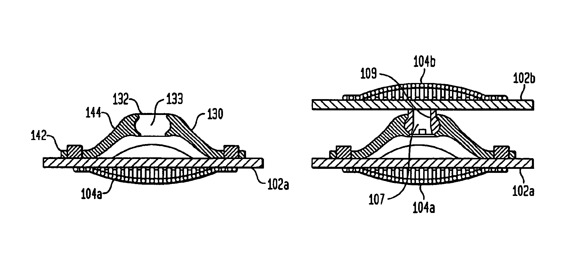
Referring also to FIG. 5, in which the fully assembled second embodiment of the present invention is shown, the combination and assembly of this embodiment is now provided. The deflectability of the ball-shaped head 107 of the post 105, prior to the insertion of the set screw 101, permits the head 107 to be inserted into the interior volume 133 at the peak of the domed arch strip spring 130. Subsequent introduction of the set screw 101 into the axial bore 109 of the post 101 flexibly couples the head 107 to the spring 130 by virtue of the head 107 not being compressible and removable from the central volume 133, but the post 105 being polyaxially retained in the socket 133. Ideally the post head 107 is locked loosely enough within the central volume 133 of the spring 130 such that anatomically relevant rotation of the plates 100a,100b remains viable. In alternative variation, however, it is possible to design the coupling such that the locking of the set screw 101 in the head 107 lo...


PUM

PropertyMeasurementUnit
Forceaaaaaaaaaa
Volumeaaaaaaaaaa

Abstract

An intervertebral spacer device having a pair of opposing plates for seating against opposing vertebral bone surfaces, separated by a spring mechanism. The preferred spring mechanism is a domed arched strip spring which is coupled to the upper plate by set screws. The spring includes a socket formed in the peak thereof and mounts onto a ball-shaped head extending outwardly from the lower plate. The spring and post members are thereby flexibly coupled such that the upper and lower plates may rotate relative to one another.

Description

FIELD OF THE INVENTIONThis invention relates generally to a spinal implant assembly for implantation into the intervertebral space between adjacent vertebral bones to simultaneously provide stabilization and continued flexibility and proper anatomical motion.BACKGROUND OF THE INVENTIONThe bones and connective tissue of an adult human spinal column consists of more than 20 discrete bones coupled sequentially to one another by a tri-joint complex which consists of an anterior disc and the two posterior facet joints, the anterior discs of adjacent bones being cushioned by cartilage spacers referred to as intervertebral discs. These more than 20 bones are anatomically categorized as being members of one of four classifications: cervical, thoracic, lumbar, or sacral. The cervical portion of the spine, which comprises the top of the spine, up to the base of the skull, includes the first 7 vertebrae. The intermediate 12 bones are the thoracic vertebrae, and connect to the lower spine compr...

Claims


Application Information

Patent Timeline
IPC IPC(8): A61F2/44A61F2/00A61F2/30
CPCA61F2/442A61F2/4425A61F2/30742Y10S606/907A61F2002/30133A61F2002/30171A61F2002/302A61F2002/30433A61F2002/30443A61F2002/30444A61F2002/30451A61F2002/30492A61F2002/30502A61F2002/30507A61F2002/30518A61F2002/30565A61F2002/30571A61F2002/30594A61F2002/30604A61F2002/30649A61F2002/30769A61F2002/30774A61F2002/30909A61F2002/3092A61F2002/30975A61F2002/443A61F2220/0025A61F2220/0041A61F2220/0058A61F2230/0015A61F2230/005A61F2230/0065A61F2310/00017A61F2310/00023A61F2310/00365A61F2/30767A61F2002/305
Inventor RALPH, JAMES D.TATAR, STEPHENERRICO, JOSEPH P.
Owner HOWMEDICA OSTEONICS CORP
Why Eureka
Try Eureka