Eureka AIR delivers breakthrough ideas for toughest innovation challenges, trusted by R&D personnel around the world.

Chip-type LED and process of manufacturing the same

a chip-type led and manufacturing process technology, applied in the field of chip-type led, can solve the problems of thermal stress to the junction between the molded object, color unevenness, and difficulty in completely avoiding color unevenness

Inactive Publication Date: 2005-03-22
SHARP KK
View PDF20 Cites 34 Cited by
  • Summary
  • Abstract
  • Description
  • Claims
  • Application Information

AI Technical Summary

Benefits of technology

Under the above-mentioned circumstances, the present invention have been achieved to provide a chip-type LED which is resistant to an externally applied thermal stress, hardly causes unevenness in color even in the case of emitting white light and scarcely decomposes a light-transmissive resin even if it is used in combination with an LED element emitting the ultraviolet light, and a process of manufacturing the same.

Problems solved by technology

This may cause a thermal stress to a junction between the molded article and the light-transmissive resin, the LED element itself and a gold wire connecting the LED element and the lead frames.
Such a problem is caused by the specific gravity of the inorganic fluorescent material that is greater than that of the organic epoxy resin.
As a result, when the opening of the concave portion is viewed from the top, a portion of strong blue light and a portion of strong yellow light are observed, thereby generating unevenness in color.
Even if the fluorescent material concentration in the light-transmissive resin is uniform, it is still difficult to completely avoid the unevenness in color because there is a difference in distance across the fluorescent material covered by light emitted from the upper surface of the LED element and that covered by light emitted from the side surface thereof.
Further, when the LED element which emits ultraviolet light such as bluish-purple light is utilized, luminance is lowered and the resulting LED would not be suitable for practical use because the light-transmissive resin such as the epoxy resin is decomposed by the ultraviolet light and turned yellow or black.

Method used


Image

  • Chip-type LED and process of manufacturing the same
  • Chip-type LED and process of manufacturing the same
  • Chip-type LED and process of manufacturing the same

Examples


embodiment 1

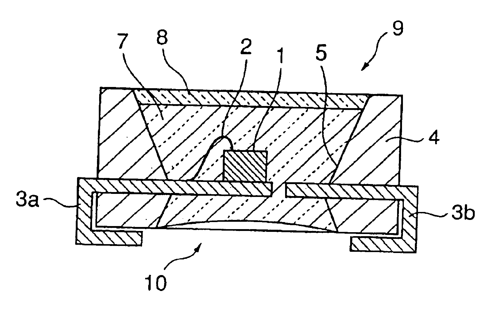
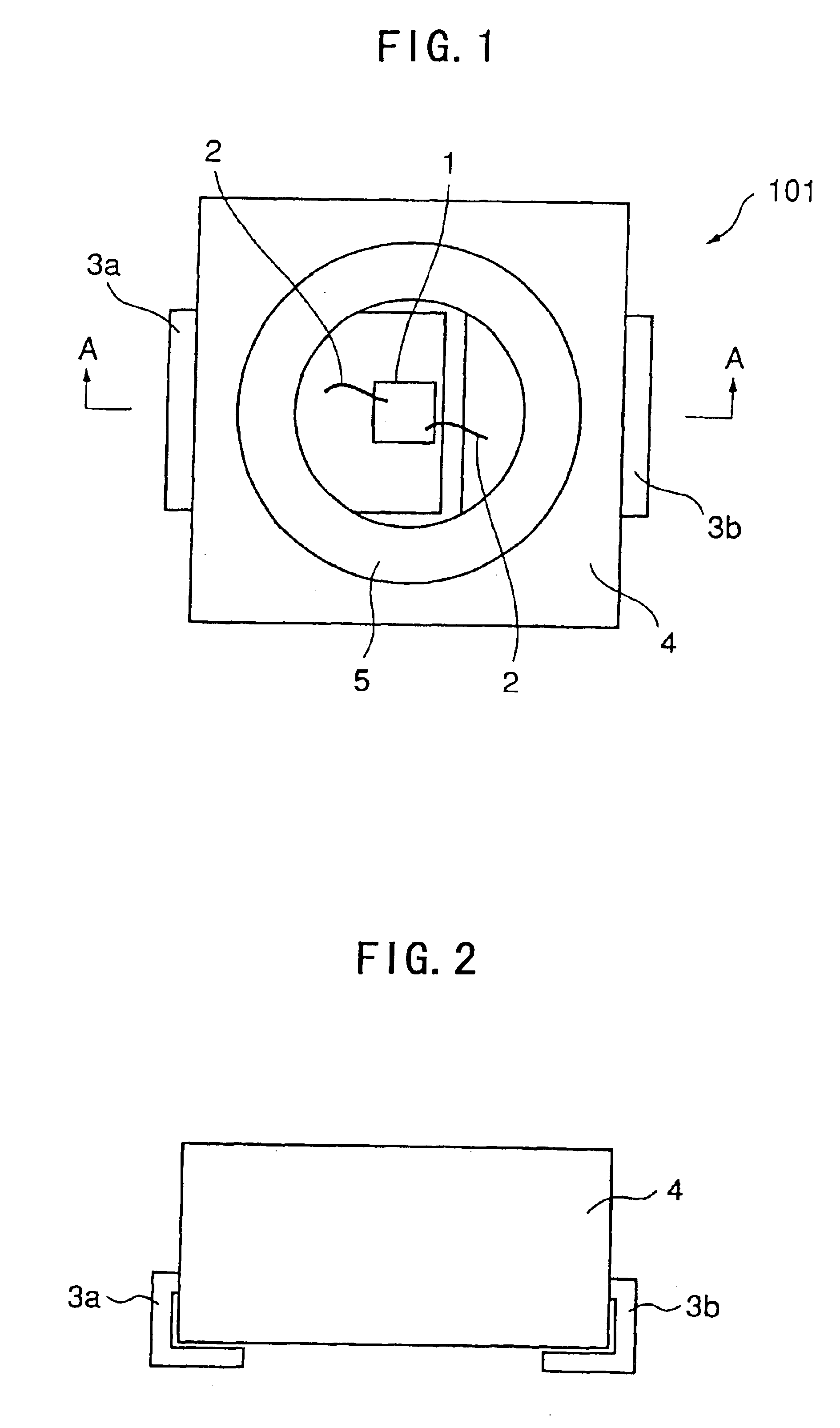
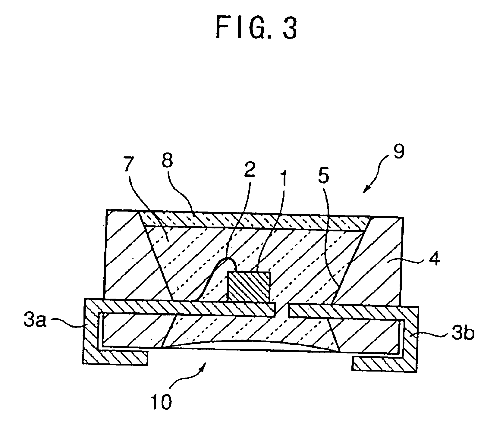
A chip-type LED according to Embodiment 1 of the present invention is explained with reference to FIGS. 1 to 4. FIG. 1 is a plan view of the chip-type LED according to Embodiment 1 of the present invention, FIG. 2 is a front view of the same, FIG. 3 is a section taken along the line A—A shown in FIG. 1, and FIGS. 4(a) and 4(b) are views illustrating the steps of manufacturing the chip-type LED according to Embodiment 1.

As shown in FIGS. 1 to 3, the chip-type LED 101 according to Embodiment 1 of the present invention comprises a LED element 1 and tubular vessel 4 accommodating the LED element 1 therein. The vessel 4 has an upper opening 9 and a lower opening 10, the LED element 1 is positioned between the upper opening 9 and the lower opening 10 such that the LED element 1 emits light toward the upper opening 9, and the vessel 4 is filled with a light-transmissive resin 7 from the upper opening 9 to the lower opening 10. The chip type LED 101 further comprises a first lead frame 3a a...

embodiment 2

A chip-type LED according to Embodiment 2 of the present invention is explained with reference to FIGS. 5 to 8. FIG. 5 is a plan view of the chip-type LED according to Embodiment 2 of the present invention, FIG. 6 is a front view of the same, FIG. 7 is a section taken along the line B—B shown in FIG. 5. FIGS. 8(a) and 8(b) are views illustrating the steps of manufacturing the chip-type LED according to Embodiment 2 of the present invention.

In the chip-type LED according to Embodiment 2, components same as those in the chip-type LED according to Embodiment 1 are given with the same reference numerals.

As shown in FIGS. 5 to 7, the chip-type LED 201 according to Embodiment 2 of the present invention includes a light-transmissive resin 7 formed to have a convex lens portion at an upper opening 9. Other components are arranged in the same manner as in the chip-type LED 101 according to Embodiment 1.

The step of forming the fluorescent layer 8 and the step of filling the light-transmissive...

embodiment 3

A chip-type LED according to Embodiment 3 of the present invention is explained with reference to FIGS. 9 to 11. FIG. 9 is a plan view of the chip-type LED according to Embodiment 3 of the present invention, FIG. 10 is a front view of the same, FIG. 11 is a section taken along the line C—C shown in FIG. 9. In the chip-type LED according to Embodiment 3, components same as those in the chip-type LEDs according to Embodiments 1 and 2 are given with the same reference numerals.

As shown in FIGS. 9 to 11, the chip-type LED 301 according to Embodiment 3 of the present invention comprises a LED element 1 for emitting bluish-purple light, a pot-shaped cup 15 for accommodating the LED element 1 therein, a tubular vessel 4 having an upper opening 9 and a lower opening 10 and accommodating the cup 15 therein, a light-transmissive resin (member) 7 for sealing the upper opening 9 of the vessel 4, a fluorescent layer 8 for converting the bluish-purple light to yellow light, and a first lead frame...


PUM

PropertyMeasurementUnit
wavelengthsaaaaaaaaaa
electrostatic breakdown voltageaaaaaaaaaa
electricallyaaaaaaaaaa

Abstract

A chip-type LED including a LED element and a tubular vessel accommodating the LED element therein, wherein the vessel has an upper opening and a lower opening, the LED element is positioned between the upper opening and the lower opening such that the LED element emits light toward the upper opening, and the vessel is filled with a light-transmissive resin from the upper opening to the lower opening.

Description

BACKGROUND OF THE INVENTION1. Field of the InventionThe present invention relates to a chip-type LED and a process of manufacturing the same, and more particularly, it relates to a chip-type LED utilized as a light source for various display panels or a backlight source for liquid crystal display devices.2. Description of Related ArtThere has been known a common chip-type LED comprising a pair of lead frames each extending to the bottom of a concave portion of a molded article, a LED element mounted on one of the lead frames and a light-transmissive resin filled in the concave portion. Some of the chip-type LEDs utilize an LED element which emits blue or bluish-purple light and a light-transmissive resin containing a fluorescent material.The chip-type LED of this kind converts a part of the blue or bluish-purple light to yellow light and mixes the yellow light and the blue or bluish-purple light to emit white light (see Publication of Japanese Patent No. 2927279).The molded article ...

Claims


Application Information

Patent Timeline
Patent Type & Authority Patents(United States)
IPC IPC(8): H01L33/00H01L23/28H01L21/56H01L23/48H01L33/44H01L33/48H01L33/50H01L33/54H01L33/56H01L33/60H01L33/62
CPCH01L33/54H01L24/97H01L33/486Y10T29/49117H01L33/52H01L2224/48091H01L2224/48247H01L2224/48257H01L2924/01012H01L2924/01025H01L2924/01039H01L2924/01063H01L2924/01078H01L2924/01079H01L2933/0041H01L33/507Y10T29/49121H01L2224/45144H01L2924/01019H01L2924/00014H01L2924/12035H01L2924/351H01L2924/00
Inventor OKAZAKI, JUN
Owner SHARP KK
Why Eureka
Eureka Blog
Learn More