Power converter

a power converter and converter technology, applied in the direction of automatic control, process and machine control, instruments, etc., can solve the problem of difficult miniaturization of circuits, and achieve the effect of raising the freedom of circuit design

Inactive Publication Date: 2005-03-22
MATSUSHITA ELECTRIC WORKS LTD
View PDF15 Cites 12 Cited by
  • Summary
  • Abstract
  • Description
  • Claims
  • Application Information

AI Technical Summary

Benefits of technology

In view of the above problem, the object of the present invention is to provide a power converter which has little harmonic distortion and can combine miniaturization and high-efficiency.
In this case, it is possible to set the voltage of the smoothing capacitor to a desired value by selecting the turn ratio of the primary winding n1 and the secondary winding n2 appropriately, whereby, the freedom of a circuit design can be raised.

Problems solved by technology

However, because, in one of these modes, the current does not flow through the inductor and the load at the same time, energy is stored in the inductor while the current is not supplied to the load.
For this reason, the inductor and the switching elements need to withstand voltage; therefore, it was difficult to miniaturize the circuit.

Method used


Image

  • Power converter
  • Power converter
  • Power converter

Examples


sixth embodiment

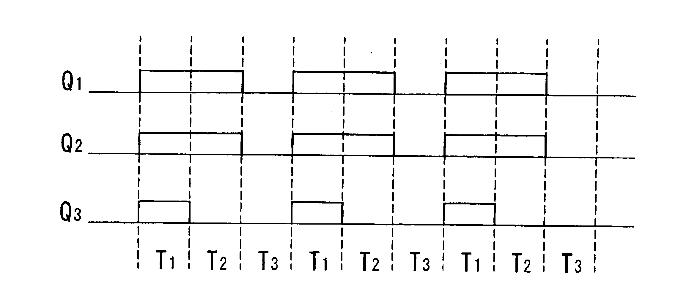
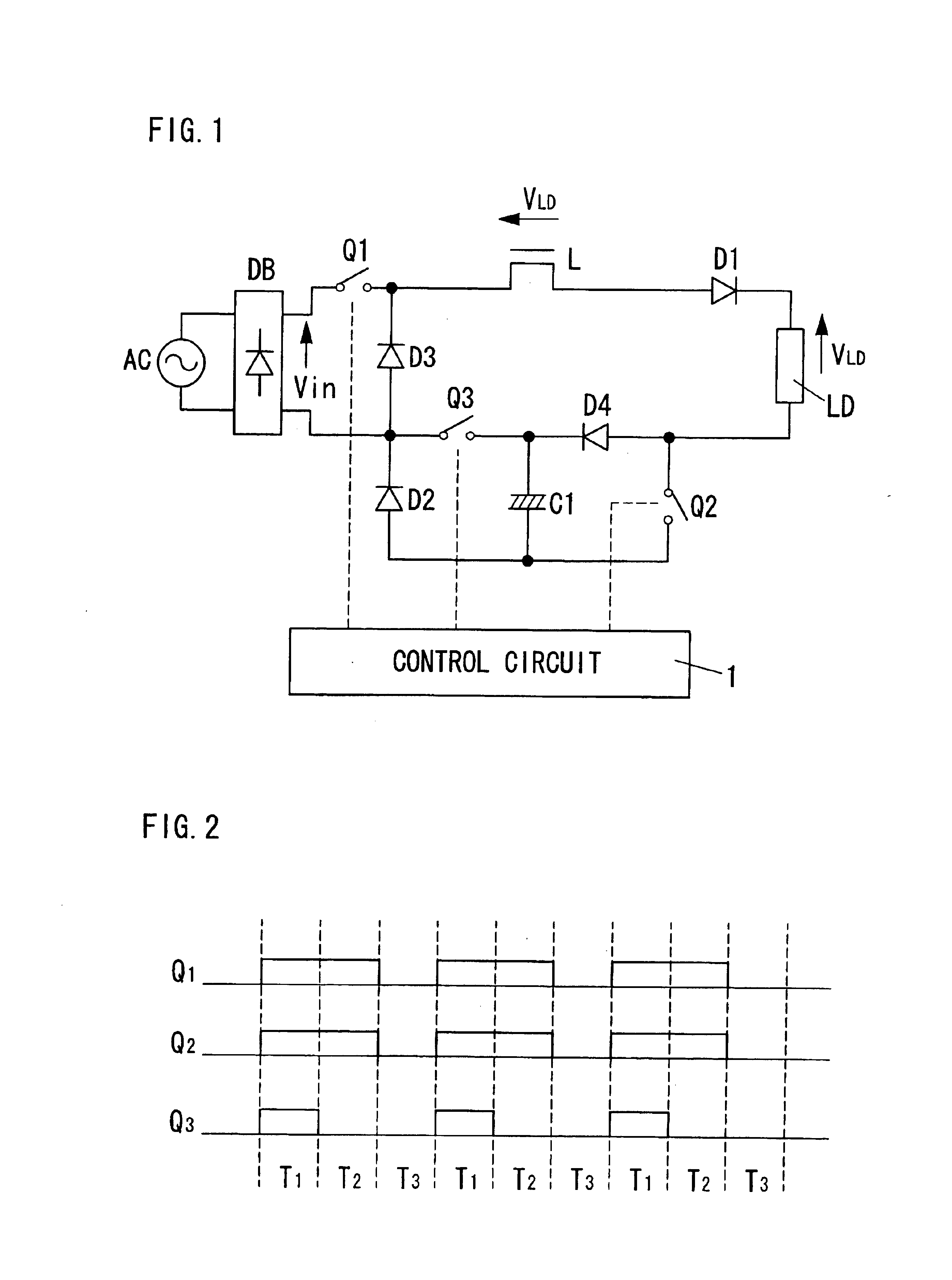
A power converter in accordance with a sixth embodiment of the present invention will be explained based on FIGS. 22-25. A circuit arrangement of the power converter is identical to the first embodiment, and a control system of the control circuit 1 is different from the first embodiment. The similar parts of these embodiments are identified by the same reference character. The control circuit 1 controls the first, second, and third switching elements Q1-Q3 in three different on / off patterns, as shown in FIG. 22. In a first pattern, the second and third switching elements Q2 and Q3 are turned on. In a second pattern, only the second switching element Q2 is turned on. In a third pattern, only the first switching element Q1 is turned on. Each switching element is turned on and off at a frequency higher enough than the frequency of the AC source (50-60 Hz), for example, dozens—several hundred kHz.

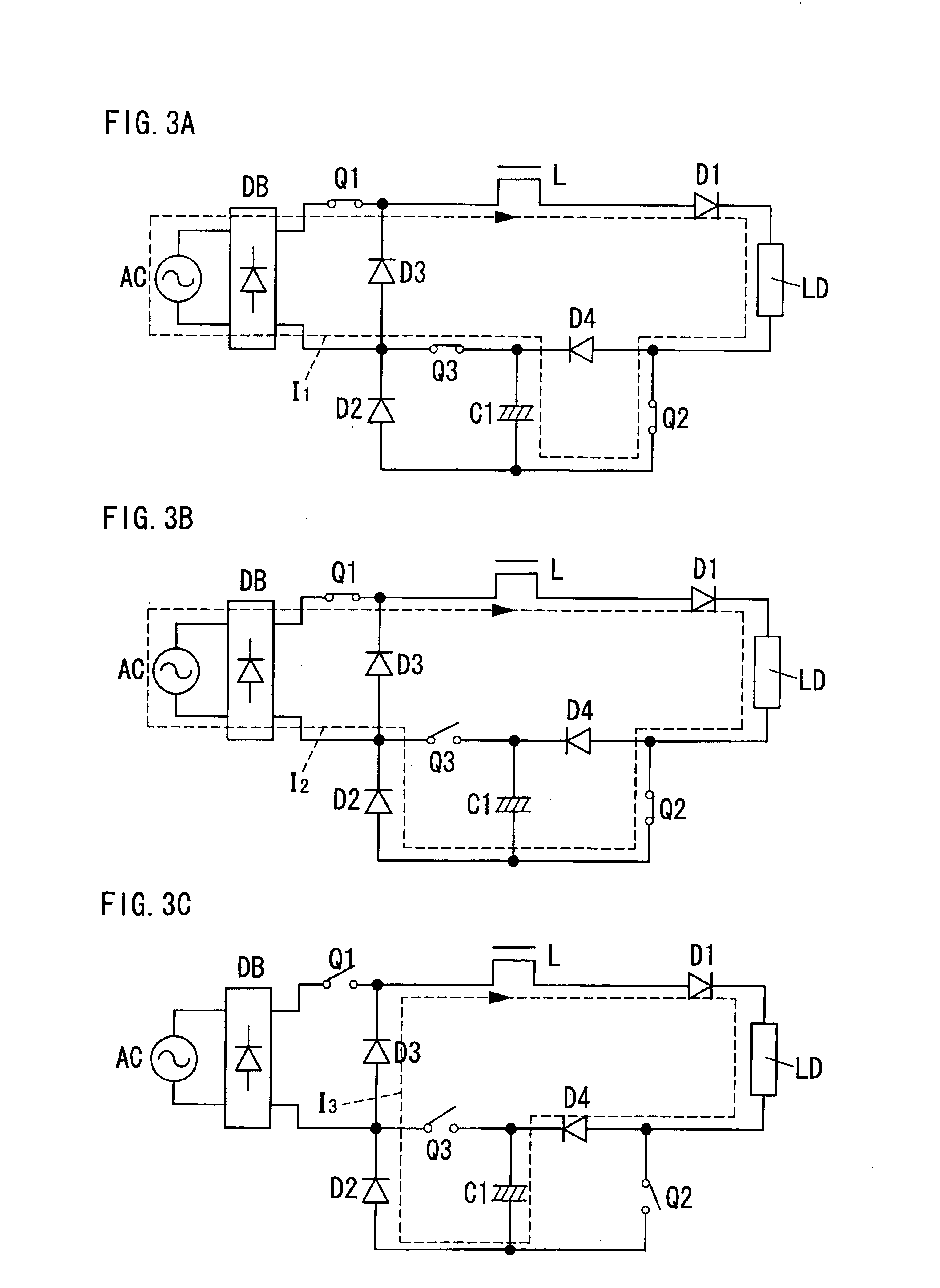
FIGS. 23A-23C show a current which flows through the circuit in a first period T1 controll...

seventh embodiment

A power converter in accordance with a seventh embodiment of the present invention will be explained based on FIGS. 26-28. This power converter is designed to convert AC power from an AC source into DC power and subsequently convert the DC power to AC power in order to supply an alternating current of rectangular wave of low frequency, for example, at 100 Hz, to a load such as a discharge lamp. This power converter includes a rectifier circuit DB which rectifies the AC current from the AC source to give a DC voltage, five switching elements Q1-Q5, one inductor L, and one smoothing capacitor C1. The first switching element Q1 and the second switching element Q2 are connected in series with a first diode across the rectifier circuit DB, and the first diode D1 is inserted between a high voltage side of the rectifier circuit DB and the first switching element Q1, and a cathode of the first diode D1 is connected to the first switching element Q1. The third switching element Q3 and the fo...

eighth embodiment

A power converter in accordance with an eighth embodiment of the present invention is shown in FIGS. 29, 30. A circuit arrangement of the power converter is identical to the seventh embodiment, and a control system of the control circuit 1 is different from the seventh embodiment. The similar parts of these embodiments are identified by the same reference character. The control circuit 1 controls the first, second, third, fourth, and fifth switching elements Q1-Q5 in six different on / off patterns as shown in FIG. 29 to always pass the current to the load and the inductor, improving the harmonic distortion, namely, a power-factor. These six patterns are classified into a positive cycle in which three continuous patterns are repeated, and a negative cycle in which remaining three continuous patterns are repeated. Each of the positive cycle and the negative cycle is repeated alternately at a low frequency, for example, at 100 Hz. FIG. 29 shows a control system to control the first, fou...


PUM

PropertyMeasurementUnit
frequencyaaaaaaaaaa
frequencyaaaaaaaaaa
frequencyaaaaaaaaaa

Abstract

This power converter comprises a plurality of switching elements, an inductor, and a smoothing capacitor. An input current of low frequency from the AC source is intermitted by the switching element turned on and off at high frequency, and an output current to a load is restricted by the inductor. These switching elements are controlled in different patterns. While these patterns are repeated, a current is always supplied to the load and inductor. Therefore, the power converter can provide a desired output power, making the inductance required for the inductor into the minimum. That is, the power converter can combine miniaturization and high-efficiency.

Description

TECHNICAL FIELDThe present invention relates to a power converter which provides an electric power for a load from an AC source.BACKGROUND ARTJapanese Non-examined Patent Publication No.8-223915 discloses a conventional power converter. This power converter changes AC power which is from an AC source into DC power, and gives the DC power to a load. A boost converter and a back converter are arranged in parallel, and either of them operates according to power-supply voltage. These two converters include a switching element, respectively, and supply a current to the load, improving harmonic distortion, by making each switching element turn on and off at a frequency higher enough than the frequency of the AC power. This power converter includes two or more switching elements and one inductor which is shared by these converters. The switching elements are controlled in different patterns in order to give a plurality of current supplying modes. By repeating these current supplying modes,...

Claims


Application Information

Patent Timeline
Patent Type & Authority Patents(United States)
IPC IPC(8): H02M3/158H02M3/04H02M7/48
CPCH02M7/48H02M3/158
Inventor IWAHORI, YUTAKA
Owner MATSUSHITA ELECTRIC WORKS LTD
Why Eureka
Try Eureka