Clamping mechanism for clamping card-shaped electronic component, and electronic apparatus having the same

a technology of electronic components and clamping mechanisms, which is applied in the direction of electrical apparatus casings/cabinets/drawers, coupling device connections, instruments, etc., and can solve problems such as limiting its miniaturization

Inactive Publication Date: 2005-03-22
FUJITSU LTD
View PDF7 Cites 15 Cited by
  • Summary
  • Abstract
  • Description
  • Claims
  • Application Information

AI Technical Summary

Benefits of technology

Accordingly, it is an exemplified general object of the present invention to provide a novel and useful ...

Problems solved by technology

The conventional clamping mechanism, however, structurally forms dead space that is not used always inside the electronic apparatus, inhibitin...

Method used


Image

  • Clamping mechanism for clamping card-shaped electronic component, and electronic apparatus having the same
  • Clamping mechanism for clamping card-shaped electronic component, and electronic apparatus having the same
  • Clamping mechanism for clamping card-shaped electronic component, and electronic apparatus having the same

Examples


Embodiment Construction

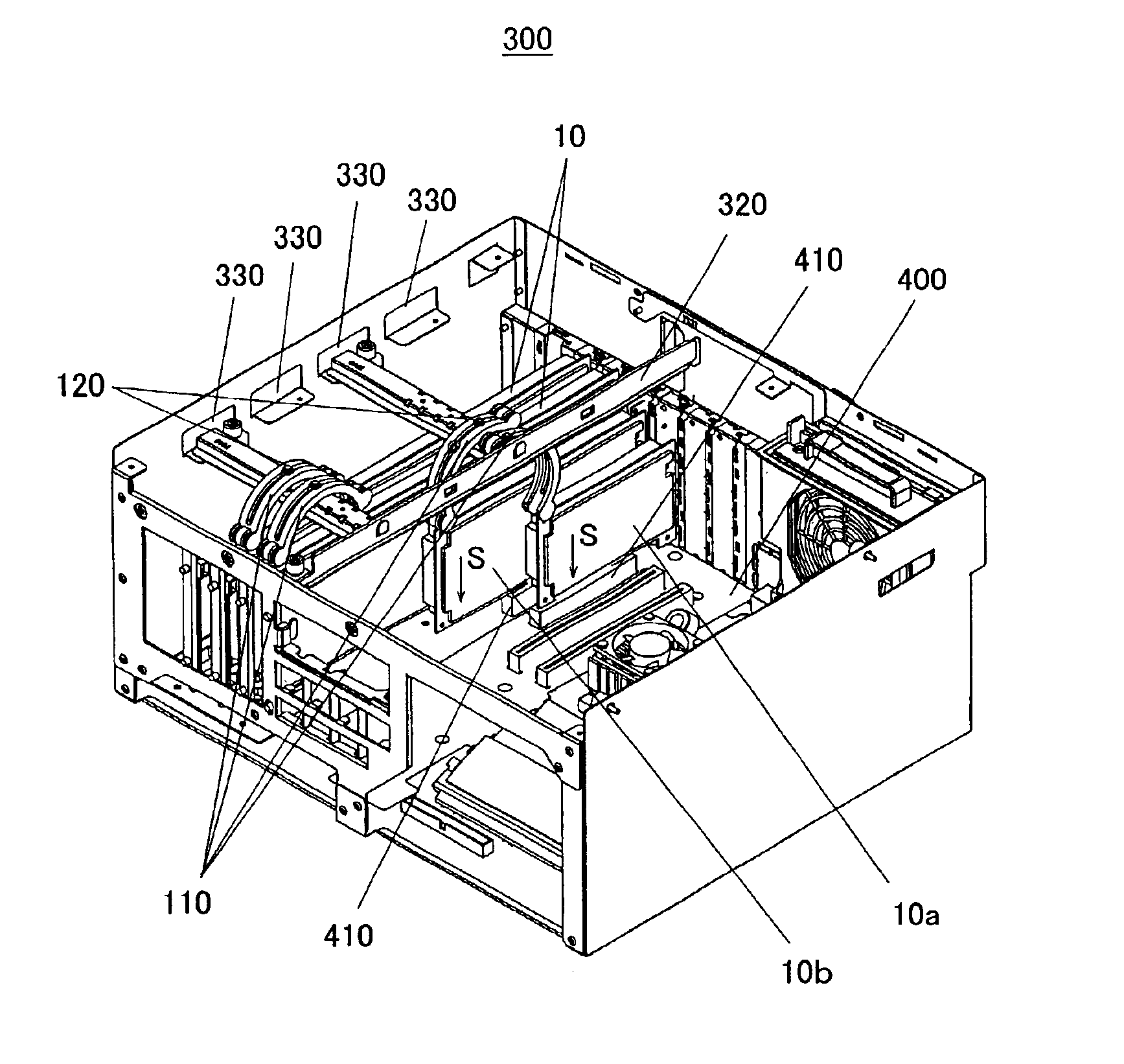
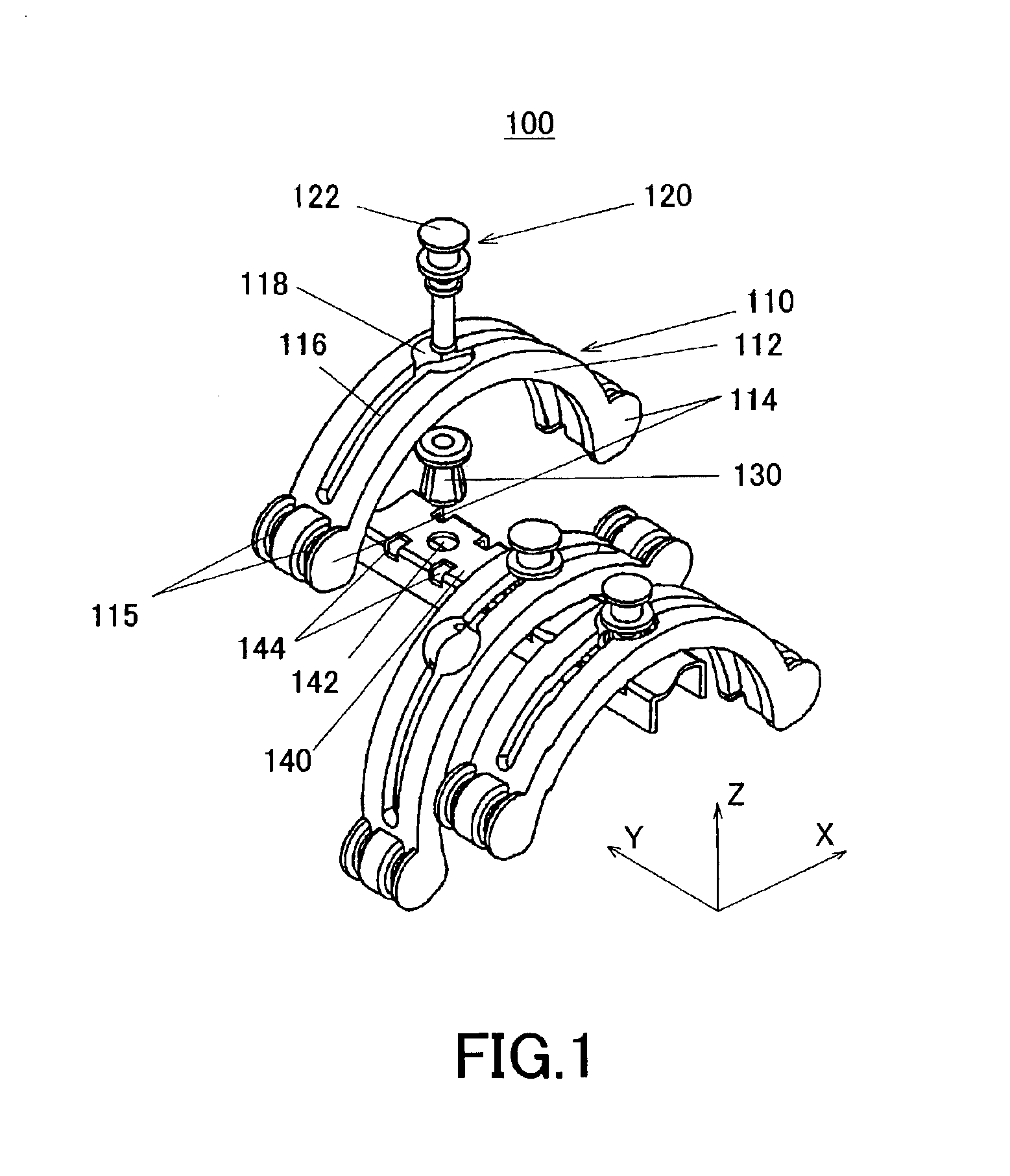
Referring now to the accompanying drawings, a description will be given of a clamping mechanism 100 for fixing the expansion card 10 as one example of a card-shaped electronic component as one aspect of the present invention. The instant specification refers to this clamping mechanism 100 as a retention unit. In each figure, the same reference numeral denotes the same element and a duplicate description will be omitted. The same reference numeral with a capital generally denotes a variation, and a reference numeral without an alphabetical letter generalizes all the reference numerals with alphabetical letters.

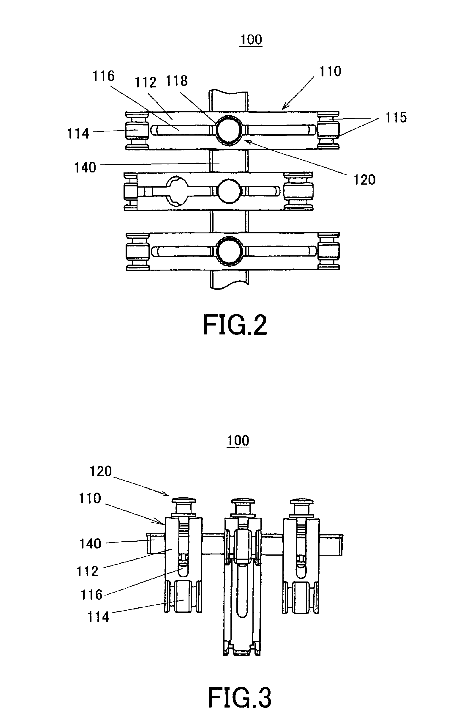
Referring to FIGS. 1 to 4, the retention unit 100 includes a retention part 110, a rivet part 120, and a bridge part 140. Here, FIG. 1 is a schematic perspective view of a retention unit 100 as one aspect of the present invention. FIG. 2 is a plane view of the retention unit 100 when it is viewed in a direction opposite to a direction Z. FIG. 3 is a side view of the retention u...


PUM


Abstract

A clamping mechanism includes a retention part that fixes a card-shaped electronic component that has been inserted into a slot in a predetermined direction for electric connection, and a support part that supports the retention part in a direction that intersects with the predetermined direction.

Description

BACKGROUND OF THE INVENTIONThe present invention relates to a clamping mechanism that fixes a card-shaped electronic component that has been inserted into a slot provided on a board or at another location, and an electronic apparatus having this clamping mechanism. The present invention is suitable, for example, for a clamping mechanism that fixes an expansion card that has been inserted into an expansion slot or an expansion bus slot on a motherboard in desktop personal computer (“PC”), a word processor, and other electronic apparatuses, and an electronic apparatus having such a clamping mechanism.A motherboard is a board provided with various circuit elements, such as a memory, a chip set, an expansion slot and a BIOS ROM as well as a CPU. The expansion card is a printed board that functionally expands a PC and other electronic apparatuses singularly or by enabling them to communicate with an external peripheral or expansion unit. An expansion card is called an expansion board or ...

Claims


Application Information

Patent Timeline
IPC IPC(8): G06F1/18H05K7/14
CPCG06F1/184G06F1/185H05K7/1429H05K7/1405G06F1/186
Inventor KOSUGI, NAOFUMIIRIE, MASARU
Owner FUJITSU LTD
Why Eureka
Try Eureka