Method of producing a branched carbon nanotube for use with an atomic force microscope

a technology of branched carbon nanotubes and microscopes, which is applied in the direction of chemically reactive gases, solid-state diffusion coatings, chemical vapor deposition coatings, etc., can solve problems such as inadequacies, and achieve the effects of superior material properties, increased stability, and extreme mechanical strength

Inactive Publication Date: 2005-03-29
BOSTON COLLEGE +2
View PDF17 Cites 23 Cited by
  • Summary
  • Abstract
  • Description
  • Claims
  • Application Information

AI Technical Summary

Benefits of technology

The branched carbon nanotube produce according to the method of the subject invention overcomes the inadequacies of the prior art methods. More specifically, the material properties of branched carbon nanotubes are superior as compared to the silicon-based probes utilized in the prior art. The branched carbon nanotubes have extreme mechanical strength and increased stability at the tip of the cantilever of the atomic force microscope. Furthermore, the branched carbon nanotube enables the AFM to repeatedly measure both the surface of the substrate and the undercut feature of the substrate with significant durability and over a long period of time without failure of the branched carbon nanotube.

Problems solved by technology

The related art is characterized by one or more inadequacy primarily due to its reliance on silicon-based probes and their tendency to fracture.

Method used


Image

  • Method of producing a branched carbon nanotube for use with an atomic force microscope
  • Method of producing a branched carbon nanotube for use with an atomic force microscope
  • Method of producing a branched carbon nanotube for use with an atomic force microscope

Examples


Embodiment Construction

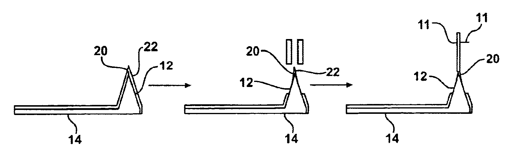
Referring to the Figures, wherein like numerals indicate like or corresponding parts throughout the several views, a method for producing a branched carbon nanotube (CNT) 11 is disclosed. The branched CNT 11 produced according to the method of the subject invention includes a primary branch, a secondary branch, and optionally, a tertiary branch. These branches are described below. By use of the terminology branch, it is to be understood that there is no requirement that the secondary branch extend perpendicular to the primary branch. Instead, the branches can be more integral to one another where the branched CNT 11 appears more like a curve than an L- or T-shape.

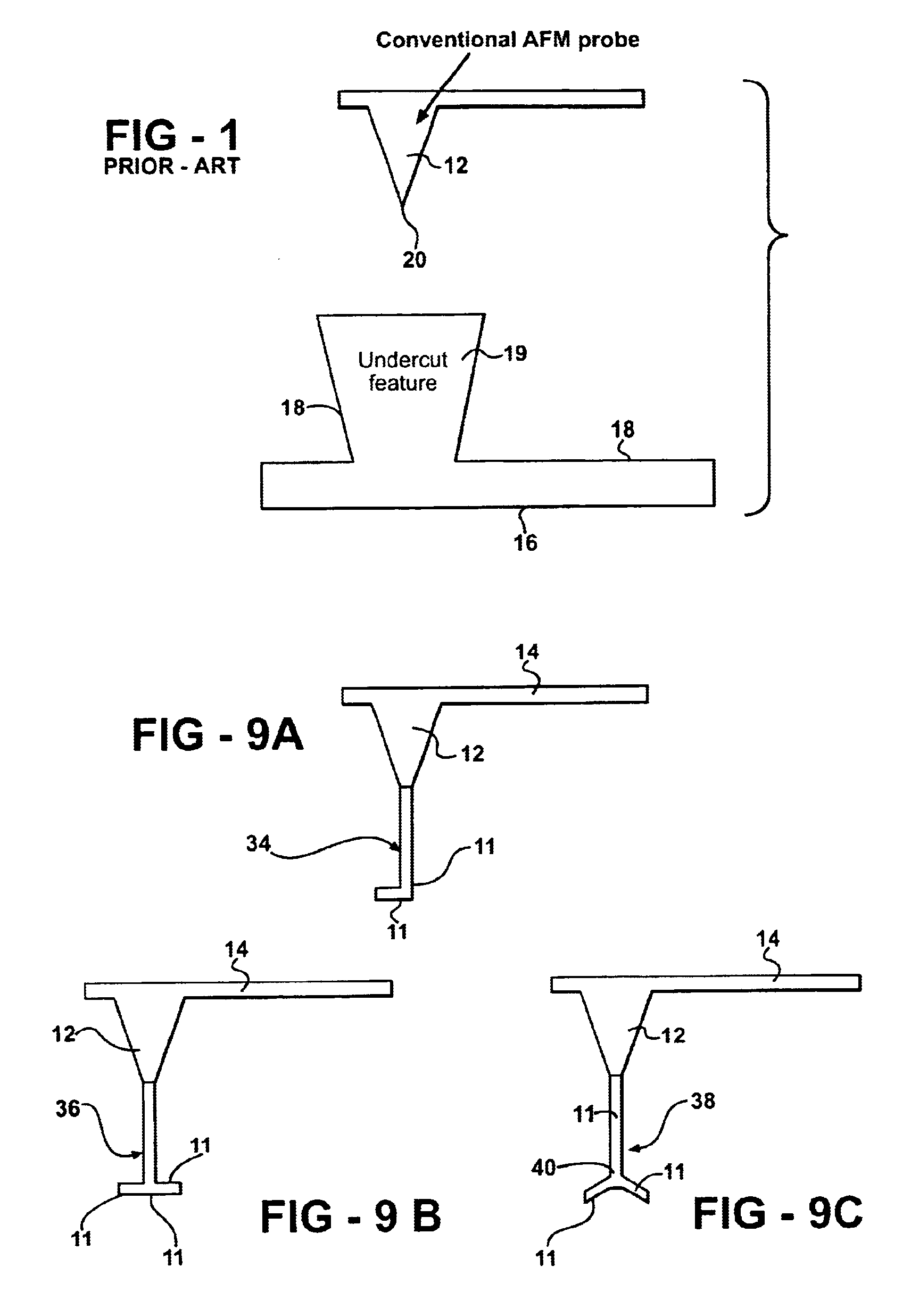
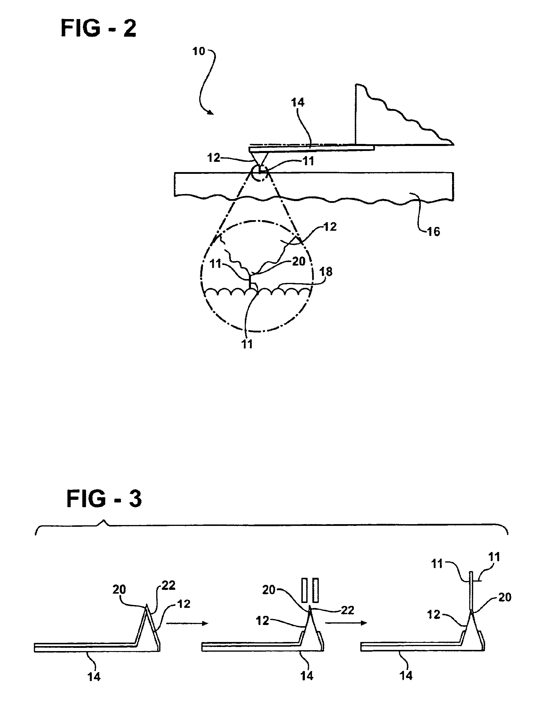
The branched CNT 11 is for use with an atomic force microscope (AFM) 10 as shown generally in FIG. 2. However, the branched CNT 11 may also be used on other devices for manipulating nanoparticles. The AFM 10 includes a cantilever 14 having a tip 12 that may, or may not, culminate with an apex 20. For example, in FIGS. 1-8 t...


PUM

PropertyMeasurementUnit
temperaturesaaaaaaaaaa
atomic force microscopeaaaaaaaaaa
electrical fieldaaaaaaaaaa

Abstract

A method of producing a branched carbon nanotube (CNT) is disclosed. The branched CNT is used with an atomic force microscope having a cantilever and a tip and that is able to measure a surface of a substrate as well as an undercut feature of the substrate that protrudes from the surface. A catalytic material is deposited onto the tip of the microscope, and the catalytic material is subjected to chemical vapor deposition. This initiates growth of a primary branch of the branched carbon nanotube such that the primary branch extends from the tip. A secondary branch is then introduced to extend from the primary branch and produce the branched carbon nanotube. The primary branch interacts with the surface of the substrate and the secondary branch interacts with the undercut feature.

Description

BACKGROUND OF THE INVENTION1. Field of the InventionThe subject invention generally relates to a method of producing a branched carbon nanotube (CNT). More specifically, the subject invention relates to a method of producing a branched CNT for use with an atomic force microscope (AFM) that is capable of measuring, i.e., dimensionally characterizing, a surface of a substrate as well as measuring an undercut feature that protrudes from the surface of the substrate.2. Description of the Related ArtThe related art includes many known methods for producing branched, specifically T-shaped, probes for use with AFMs. These convention methods produce a silicon-based probe that is used with the AFM to measure a surface of a substrate as well as an undercut feature that protrudes from the surface of the substrate. However, silicon-based probes are prone to failure due to various stress and strain issues that ultimately cause the silicon to fracture. Therefore, AFMs that utilize such silicon-ba...

Claims


Application Information

Patent Timeline
Patent Type & Authority Patents(United States)
IPC IPC(8): C01B31/00C01B31/02C23C16/04C30B25/00C23C16/26G12B21/08G12B21/00H01L51/05H01L51/30B05D5/12C23C8/00G01Q60/24G01Q70/12
CPCB82Y10/00B82Y30/00B82Y35/00B82Y40/00C01B31/0233C23C16/04C23C16/26C30B25/00G01Q70/12H01L51/0048H01L51/0545B82Y15/00C30B29/02C30B29/605Y10S977/876C01B32/162H10K85/221H10K10/466
Inventor SCHLAF, RUDIGERREN, ZHIFENG F.WEN, JIANGUOCARNAHAN, DAVID L.
Owner BOSTON COLLEGE
Why Eureka
Try Eureka