Liquid flow sensor thermal interface methods and systems

a technology of thermal interface and liquid flow sensor, which is applied in the direction of instruments, material thermal conductivity, measurement devices, etc., can solve the problems of reducing thermal efficiency and therefore signal quality, discharging power, and natural gas composition change, so as to improve measurement

Active Publication Date: 2005-03-29
HONEYWELL INT INC
View PDF12 Cites 49 Cited by
  • Summary
  • Abstract
  • Description
  • Claims
  • Application Information

AI Technical Summary

Benefits of technology

It is yet a further aspect of the present invention to provide a film that isolates a...

Problems solved by technology

For example, in a semiconductor processing system that passes a nitrogen-based gas, the nitrogen-based gas may at times be replaced by a hydrogen-based or helium-based gas, depending on the needs of the process; or in a natural gas metering system, th...

Method used


Image

  • Liquid flow sensor thermal interface methods and systems
  • Liquid flow sensor thermal interface methods and systems
  • Liquid flow sensor thermal interface methods and systems

Examples


Embodiment Construction

The particular values and configurations discussed in these non-limiting examples can be varied and are cited merely to illustrate at least one embodiment of the present invention and are not intended to limit the scope of the invention.

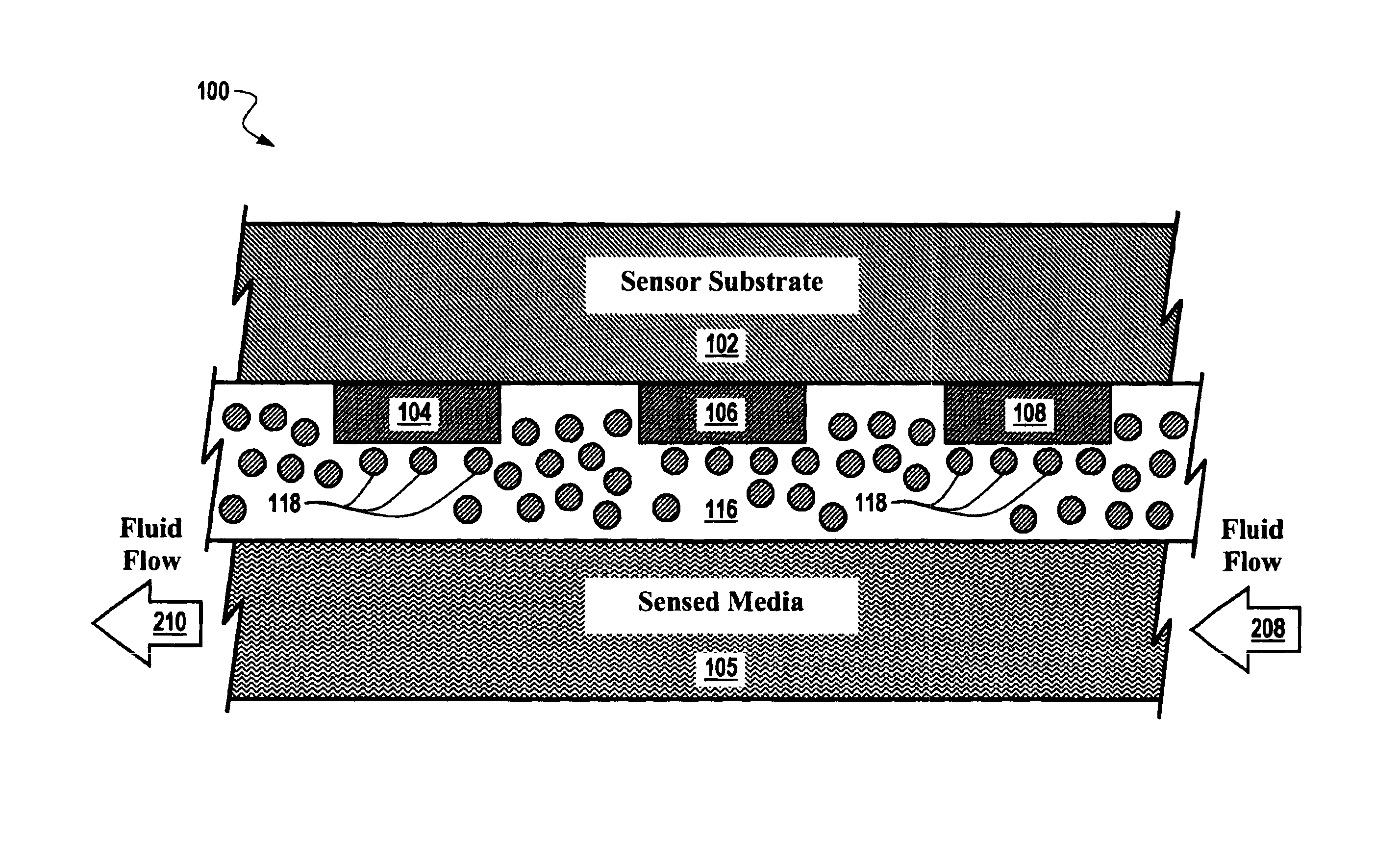
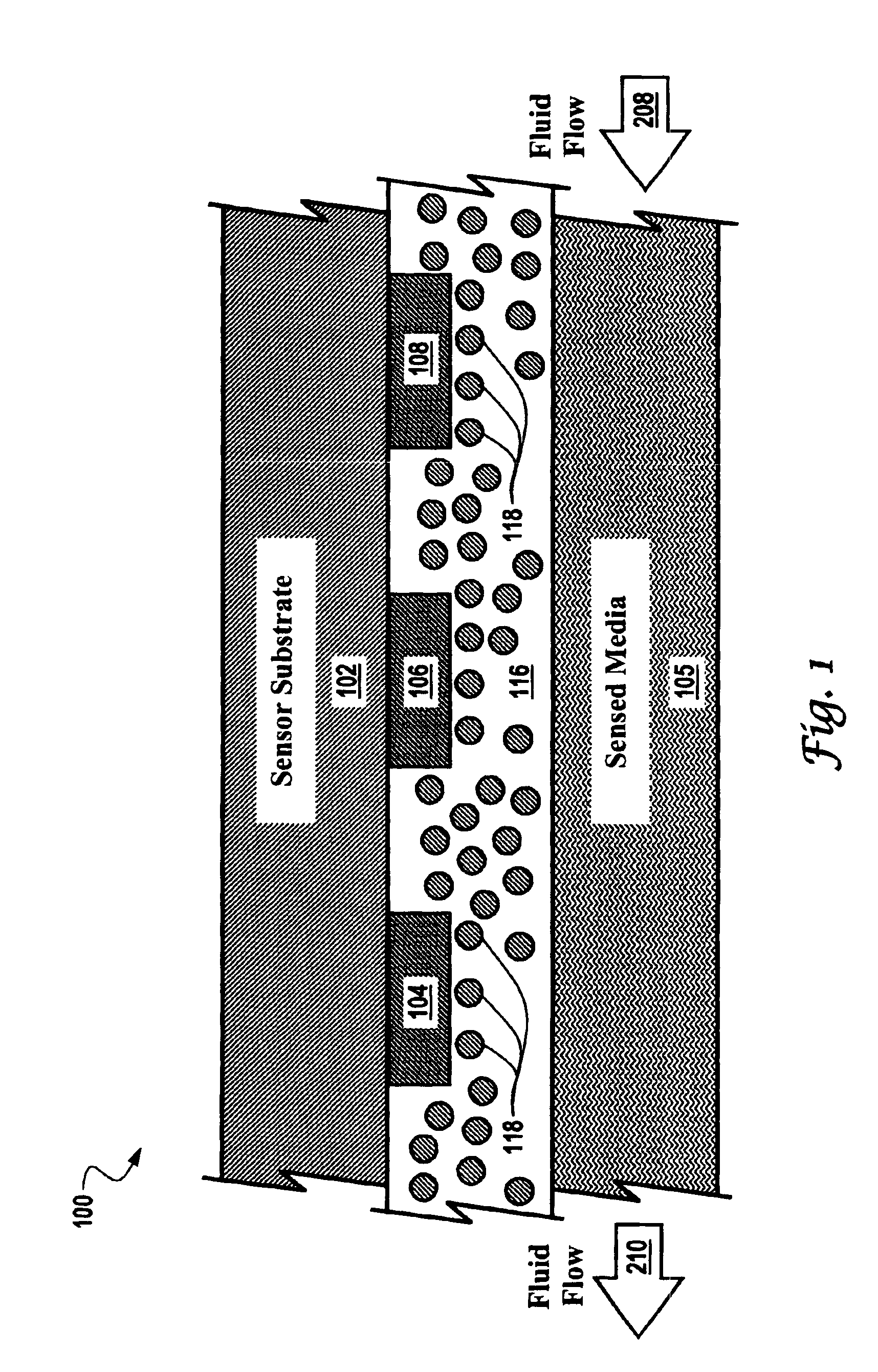
FIG. 1 illustrates a block diagram of a sensor system 100, which can be implemented in accordance with an embodiment of the present invention. System 100 comprises a low thermal conductivity tubing 116 with a plurality of thermally conductive particles 118 within the walls of tubing 116. A plurality of sensing elements 104 and 108 can be disposed along a sensor substrate 102 opposite sensed media 105. Although a single sensor substrate 102 and sensed media 105 are depicted in system 100 of FIG. 1, it can be appreciated that alternative embodiments thereof can be configured to function with one or more such sensor substrates and one or more sets of associated sensor elements.

Sensed media 105 can be, for example, a liquid such as saline or another equi...


PUM


Abstract

A sensor method and system are disclosed. A fluid flow sensor can be provided, which measures the thermal conductivity of a fluid. The sensor itself can be configured to comprise one or more sensing element associated with a sensor substrate. A heater can be associated with said sensor wherein said heater provides heat to said fluid. A film component can also be provided that that isolates said fluid from said heater and said sensor, such that said film component conducts heat in a direction from said heater to said sensor, thereby forming a thermal coupling between said sensor, said heater and said fluid, which permits said sensor to determine a composition of said fluid by measuring thermal conductivity thereof without undesired losses of heat in other directions. The film component can be configured on or in the shape of a tubing or a flow channel.

Description

TECHNICAL FIELDEmbodiments are generally related to sensing methods and systems. Embodiments are also related to fluid flow sensors. Embodiments are additionally related to flow channels and tubing devices utilized in association with fluid flow sensors.BACKGROUND OF THE INVENTIONSensors have been used to measure flow rates in various medical, process, and industrial applications, ranging from portable ventilators supplying anesthetizing agents to large-scale processing plants in a chemical plant. In these applications, flow control is an inherent aspect of proper operation, which is achieved in part by using flow sensors to measure the flow rate of a fluid within the flow system. In many flow systems, e.g., fuel cell flow systems containing a binary mixture of methanol and water, the chemical composition of the fluid may change frequently.A flow system is often required to flow more than one fluid having different chemical and thermo physical properties. For example, in a semicondu...

Claims


Application Information

Patent Timeline
IPC IPC(8): G01F1/684G01N25/18
CPCG01N25/18G01F1/6847
Inventor GEHMAN, RICHARD W.ALDERMAN, RICHARD A.SPELDRICH, BRIAN D.
Owner HONEYWELL INT INC
Why Eureka
Try Eureka