Tool for smoothing a workpiece

a workpiece and tool technology, applied in the field of tools, to achieve the effect of reducing the amount of accumulation and roughness, ensuring the safety of use, and not excessively erode the tooth surfa

Inactive Publication Date: 2005-03-29
HARREL STEPHEN K
View PDF14 Cites 5 Cited by
  • Summary
  • Abstract
  • Description
  • Claims
  • Application Information

AI Technical Summary

Benefits of technology

In accordance with the invention, a scaler tip which can be of various shapes, includes a metal tip having one or more shallow depressions on the portion of the tip that contacts the tooth surface. Within these depressions is an active surface that has formed an abrasive or cutting surface. This active surface may include either a coating of abrasive material such as diamond grit, or a sharpened edge of the metal of the scaler tip. The diamond grit or sharpened edge does not extend above the smooth safe areas of the scaler tip. By limiting the areas covered by the abrasive, the scaler tip of the invention is safe for use on the tooth surface and does not excessively erode the tooth surface. The metal portion of the scaler tip that comes in contact with the tooth surface has a smooth surface and rounded edges, in the same manner as most existing scaler tips. Additionally, the smooth surface of the scaler tip will effectively protect the tooth and root surfaces from the abrasive or sharpened edges that are located in the shallow depressions formed in the smooth metal surface. However, rough uneven accretions of tartar or other roughness on the tooth surface will project into the shallow depressions and come in contact with the abrasive or sharp edges in the shallow grooves. The rough uneven material on the tooth will thus be rapidly removed by the abrasive or sharpened edges, thereby leaving a smooth surface. Thereafter, only the smooth, non-abrasive metal surface of the scaler will come...

Problems solved by technology

However, rough uneven accretions of tartar or other roughness on the tooth surface will project i...

Method used


Image

  • Tool for smoothing a workpiece
  • Tool for smoothing a workpiece
  • Tool for smoothing a workpiece

Examples


Embodiment Construction

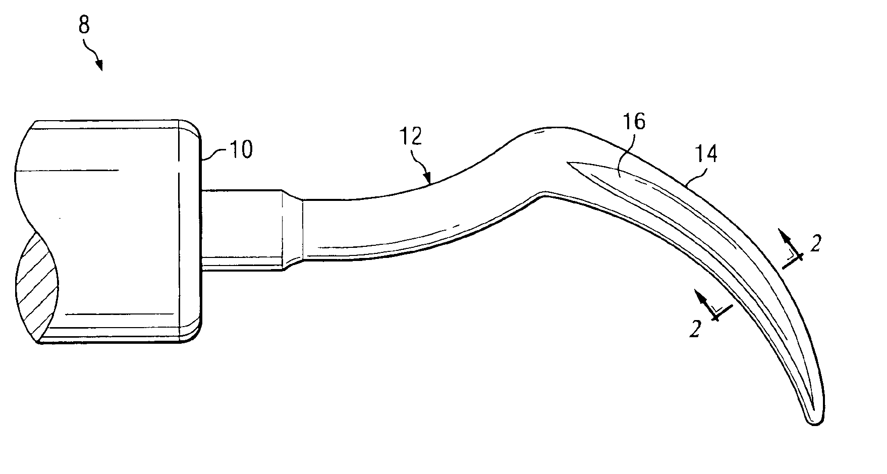
While the tool constructed according to the invention is described below in connection with an ultrasonic tip utilized in periodontal operations, the principles and concepts can be employed on tools that are applicable for use in many other areas and trades. Also, while the operation of the ultrasonic tool described below is in conjunction with movement by way of ultrasonic vibrations, tools constructed in accordance with the invention can also be moved on the workpiece by other mechanisms, such as rotary, circular, reciprocatory, hand moved, or any other action by which one or the other of the tool or the workpiece is moved with respect to the other. Tools that vibrate at frequencies other than ultrasonic, such as vibrations in the sonic frequency range, can employ the principles and concepts of the invention.

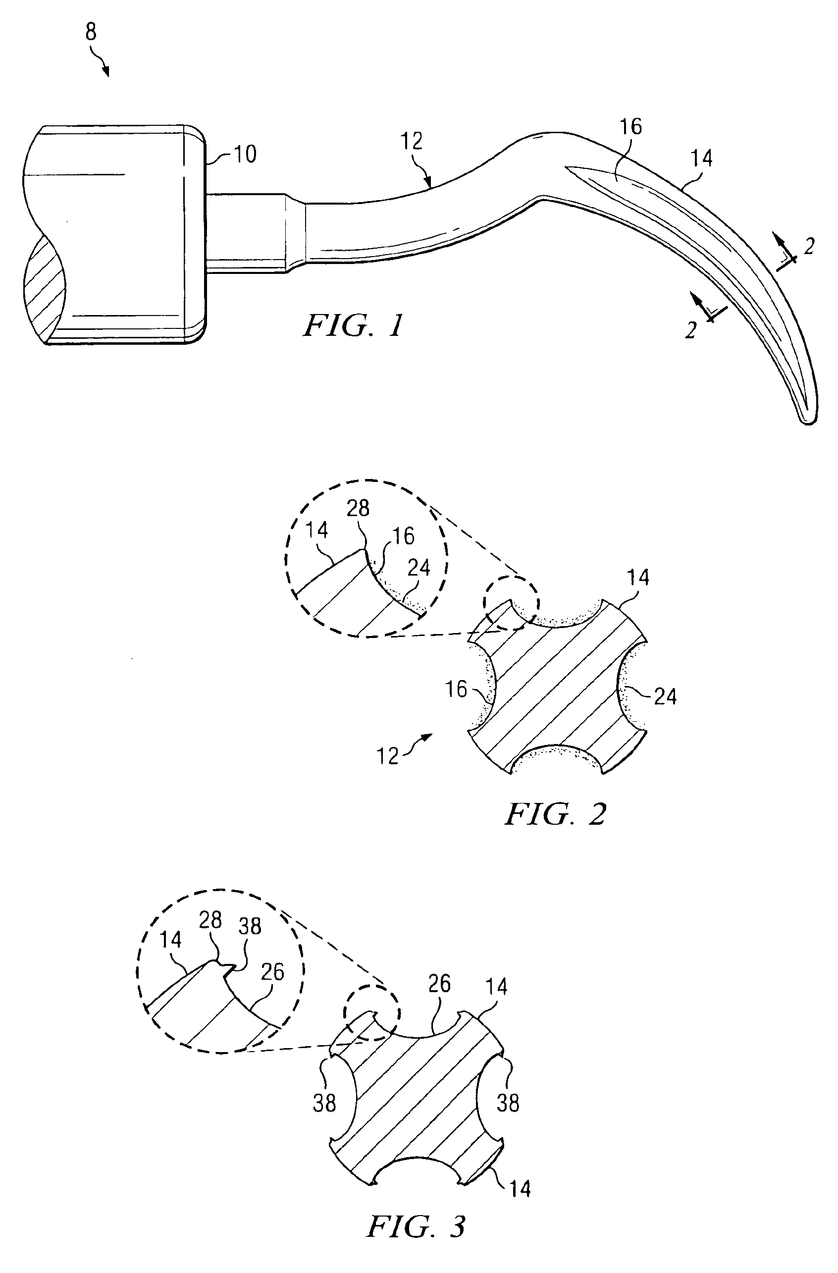
FIG. 1 illustrates a preferred form of an ultrasonic insert 8, comprising a metal scaler tip 12 constructed similar to those that are routinely attached to ultrasonic generato...


PUM

PropertyMeasurementUnit
Depthaaaaaaaaaa
Depthaaaaaaaaaa
Shapeaaaaaaaaaa

Abstract

A tool for abrading a workpiece to smooth the surface thereof. The tool has a shank portion and a working portion. The working portion has a smooth and non-abrading surface, with one or more depressions formed therein. Each depression includes an abrading mechanism. The abrading mechanism does not protrude above the smooth surface of the working portion of the tool. During operation, once the workpiece has been smoothed by removal of the raised areas by the abrading mechanism, the smooth surface of the tool engages the workpiece and further abrasion of the workpiece is prevented.

Description

TECHNICAL FIELD OF THE INVENTIONThe present invention relates in general to tools that are moveable on work surfaces to perform operations thereon, and more particularly to tools of the type having safe areas and active areas to remove rough surface areas and provide a smooth surface.BACKGROUND OF THE INVENTIONTools are utilized by many different crafts persons for working on various types of materials to fabricate an object with the desired shape or form. While the majority of tools are utilized by machinists and other crafts persons working in similar trades, various types of tools are also utilized on a daily basis by artists, carpenters, cabinet makers, engineers, physicians, dentists, etc. Depending on the application to which the tool is applied, the particular devices may be moved by hand, rotated, reciprocated or otherwise vibrated to operate upon the surface of the workpiece.In many applications, there is a need to smooth an otherwise rough workpiece surface. Hand files, sa...

Claims


Application Information

Patent Timeline
IPC IPC(8): A61C3/03A61C3/02
CPCA61C3/03Y10S451/91A61C17/20
Inventor HARREL, STEPHEN K.
Owner HARREL STEPHEN K
Why Eureka
Try Eureka