Use of configurable capacitors to tune a self biased phase locked loop

Inactive Publication Date: 2005-03-29
TEXAS INSTR INC
View PDF11 Cites 35 Cited by
  • Summary
  • Abstract
  • Description
  • Claims
  • Application Information

AI Technical Summary

Problems solved by technology

Two problems that have been identified in the optimisation are (1) the variation of component values, and therefore the dynamic parameters of the PLL, as a result of manufacturing tolerances in those components, and (2) the use of selectable frequency dividers so that the output can be at a selected multiple of the input frequency, when the dynamic parameters are usually optimised at one or more operating frequencies but not at others.

Method used


Image

  • Use of configurable capacitors to tune a self biased phase locked loop
  • Use of configurable capacitors to tune a self biased phase locked loop
  • Use of configurable capacitors to tune a self biased phase locked loop

Examples


first embodiment

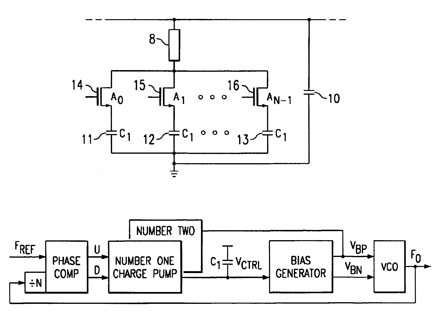
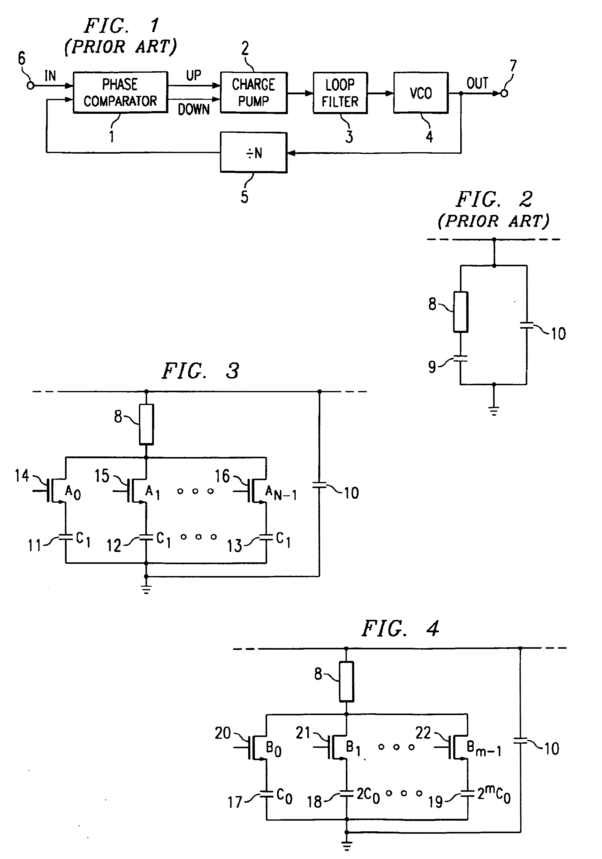
the present invention has the general form shown in FIG. 1 with a loop filter of the form shown in FIG. 2. The loop filter 3 is, however, modified by generating the first capacitor 9 from a plurality of capacitors 11, 12 and 13 that can be turned on or off using a bank of switches as shown in FIG. 3. The circuit of FIG. 3 comprises n capacitors in parallel. Each limb of the capacitor bank of FIG. 3 comprises an NMOS transistor 14, 15 and 16 and a respective capacitor 11, 12 and 13 connected between the second terminal of resistor 8 and ground.

Control signals A0, A1 . . . AN−1 are applied to the gates of transistors 14, 15 and 16 respectively. By turning on N transistors by applying suitable control signals (where N is the divider ratio), the effective capacitance of the capacitor bank (i.e. the first capacitance) is made proportional to the divider ratio N, provided that all of the capacitors 11, 12 and 13 have substantially the same capacitance (C1). This circuit is particularly su...


PUM


Abstract

A phase locked loop (PLL) comprising an input, an output, a charge generator, a low pass filter 3, an oscillator 4 and a frequency divider 5. The frequency divider 5 has an input coupled to the output of the PLL and an output coupled to an input of the charge generator. The frequency at the output of the frequency divider 5 is equal to the frequency at the input of the frequency divider divided by a selectable divider ratio N. The PLL has a damping factor z and a bandwidth to compare frequency ratio ω3 / ωref. The low pass filter 3 has a first capacitor for integrating the charge produced by the charge generator. The capacitance of that first capacitor is arranged to be proportional to the divider ratio N so that the damping factor z and the bandwidth to compare frequency ratio ω3 / ωref are substantially independent of the divider ratio N.

Description

BACKGROUND OF THE INVENTIONThe present invention relates to phase locked loops (PLLs) and more particularly to “self-biased” PLLs with dynamic parameters that are substantially independent of a PLL divider ratio. The term “self-biased PLL” is used (see the Maneatis paper cited below) to describe a PLL in which the bias current of the charge pump is self-regulating and adapts for other circuit tolerances.FIG. 1 shows a block diagram of a general form of one kind of PLL, that general form being known in the art. The circuit of FIG. 1 comprises a phase comparator 1, a charge pump 2, a loop filter 3, a voltage controlled oscillator (VCO) 4 and a frequency divider 5 and has an input 6 and an output 7. The phase comparator 1 has two inputs and two outputs. The charge pump 2 has two inputs and an output. Each one of the loop filter 3, the VCO 4 and the frequency divider 5 have an input and an output. The first input of the phase comparator 1 is coupled to the input 6 of the PLL and the sec...

Claims


Application Information

Patent Timeline
Patent Type & Authority Patents(United States)
IPC IPC(8): H03L7/093H03L7/089H03L7/08H03L7/183H03L7/16
CPCH03L7/0893H03L7/093H03L7/183H03L2207/06H03L2207/04
Inventor HARWOOD, MICHAEL
Owner TEXAS INSTR INC
Why Eureka
Try Eureka