
Power down system and method for integrated circuits

Active Publication Date: 2005-03-29
SMSC HLDG
View PDF20 Cites 23 Cited by
  • Summary
  • Abstract
  • Description
  • Claims
  • Application Information

AI Technical Summary

Benefits of technology

Other objects, advantages and features of the present invention will become more apparent upon reading of the following non-res

Problems solved by technology

The oscillator is often a crystal oscillator since it is very precise and is not sensible to environmental variations such as temperature and input voltage variations.
A drawback of using a crystal oscillator is that it requires a relatively large biais current (in the order of tens of μA) during the power down mode.
While Chapman's method and apparatus is an improvement over apparatuses using crystal oscillator during the sleep mode, it still has drawbacks related to the compensation of the ring oscillator frequency.

Method used


Image

  • Power down system and method for integrated circuits
  • Power down system and method for integrated circuits
  • Power down system and method for integrated circuits

Examples


Embodiment Construction

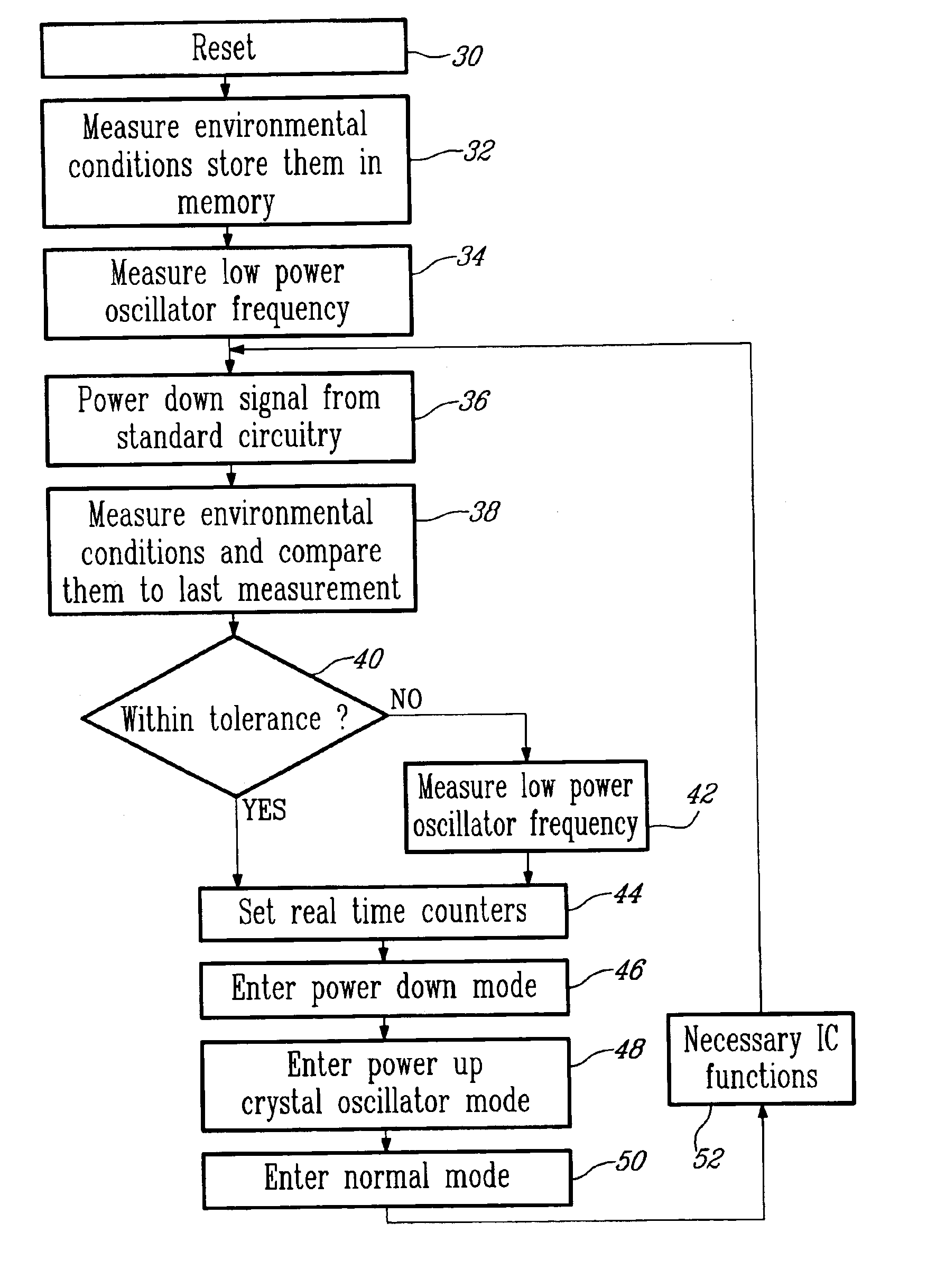
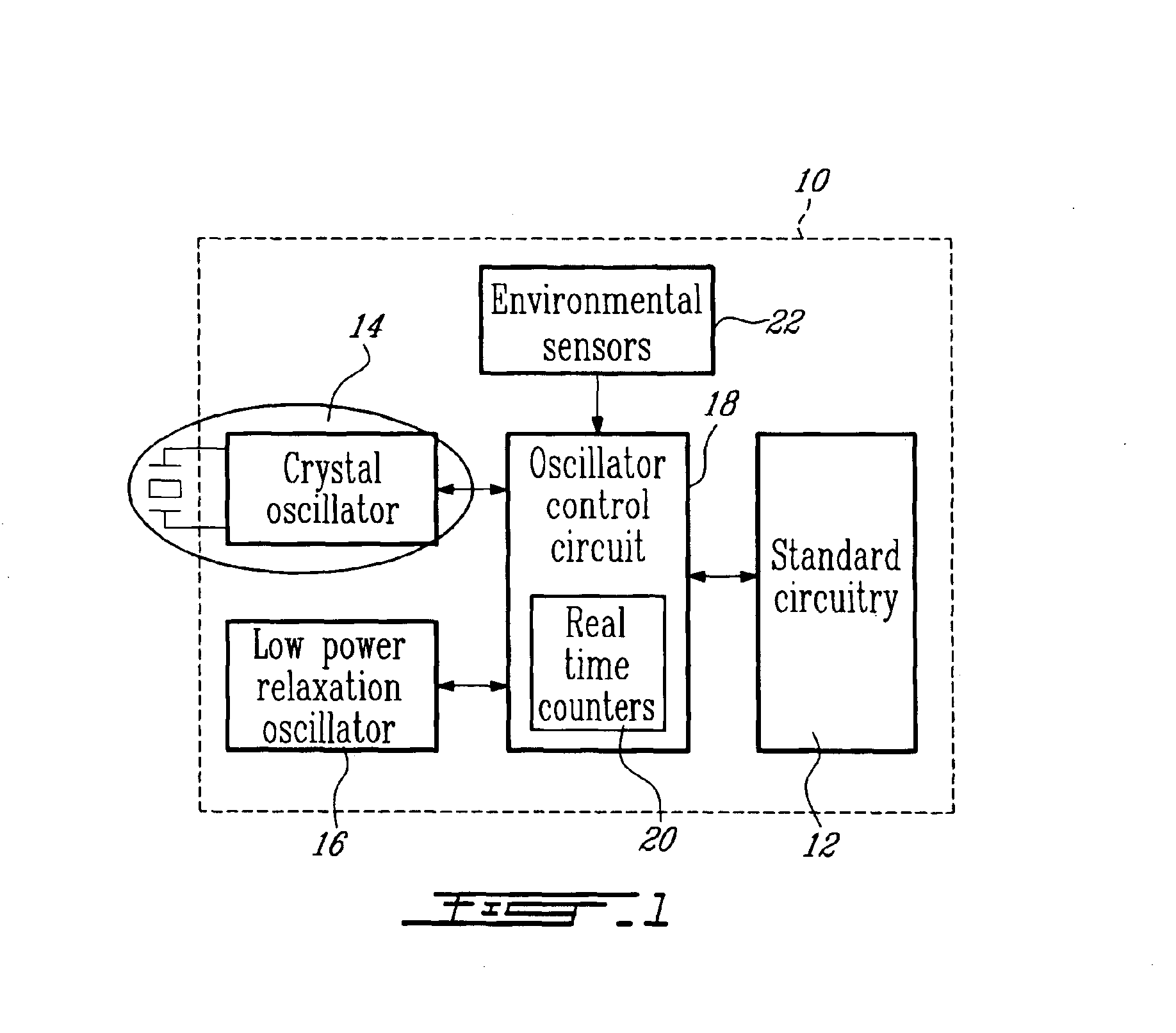
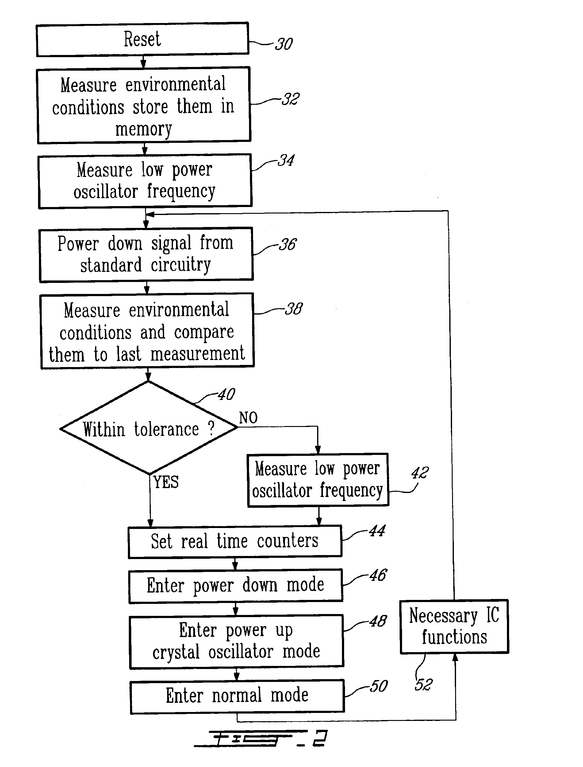
Generally, the present invention proposes a power down system and method for ICs that uses two different oscillators. A high precision oscillator, for example a crystal oscillator, is used when the IC is in its normal mode and a low power oscillator, for example a relaxation or RC oscillator, is used when the IC is in a power down mode. Since low power oscillators are usually less precise, harder to control and more sensitive to environmental changes, their frequency is measured and real time counters are adjusted so that the predetermined interval between wake-ups is maintained. The low power oscillator frequency measurement may be done at a predetermined duty cycle or can be triggered by environmental changes, as will be described hereinbelow.

Turning now to FIG. 1 of the appended drawings, an IC 10 including a power down system according to an embodiment of the present invention will be described.

The IC 10 includes standard circuitry 12 to enable the IC 10 to perform its intended ...


PUM


Abstract

A power down system and method for an integrated circuit that enables a power down mode to be maintained for a predetermined time is described herein. The power down system comprises an oscillator, a low power oscillator and an oscillator control circuit controlling both the oscillator and the low power oscillator. The oscillator control circuit including at least one real time counter. The oscillator control circuit being so configured that the oscillator is energized when said oscillator control circuit is in a normal mode and that, when a power down signal is received: a) the oscillator control circuit measures an oscillation frequency of the low power oscillator, b) the oscillator control circuit uses the measured oscillation frequency of the low power oscillator to set the real time counter so as to maintain the power down mode for the predetermined time, c) the oscillator control circuit turns off the oscillator and uses the low power oscillator for the duration of the power down.

Description

FIELD OF THE INVENTIONThe present invention relates to Integrated Circuits (ICs). More specifically, the present invention is concerned with a power down system and method for ICs.BACKGROUND OF THE INVENTIONMany ICs have a power down mode that is used to save power and, in the case of battery powered environments, extend the battery life of the system.The transition from the power down mode to the normal mode is usually controlled by an external interrupt signal or is pre-programmed at fixed intervals. The latter case is most common in sand alone systems where an IC must “wake up” at predetermined intervals to perform functions such as monitor sensors or communicate with other devices, for example.When an IC is required to wake-up at known intervals, some circuitry is required to be operating even during the power down mode to keep track of time and to wake the IC up. This circuitry usually includes an oscillator that is sufficiently precise and a real time counter. The oscillator i...

Claims


Application Information

Patent Timeline
IPC IPC(8): G06F1/32G06F1/14H04B1/16H03L3/00G06F1/04
CPCG06F1/14G06F1/3246G06F1/3228
Inventor DEVRIES, CHRISTOPHER ANDREWMASON, RALPH DICKSON
Owner SMSC HLDG
Learn More