
Adaptive fan controller for a computer system

a computer system and fan controller technology, applied in the direction of motor/generator/converter stopper, dynamo-electric converter control, instruments, etc., can solve the problems of degrading the overall performance of the computer system, noise level, and fans, and achieve the effect of reducing the noise of fans and louder sound levels

Inactive Publication Date: 2005-03-29
TELEFON AB LM ERICSSON (PUBL)
View PDF9 Cites 65 Cited by
  • Summary
  • Abstract
  • Description
  • Claims
  • Application Information

AI Technical Summary

Benefits of technology

The patent describes a temperature control system for electronics that reduces fan noise. The system uses multiple protocols that specify fan speed based on temperature. When the system initializes, it selects a quieter protocol to cool the system. If the temperature reaches a certain threshold, the system will switch to a different protocol that is better at cooling, but will result in a louder sound level. This system aims to keep the cooling system as quiet as possible. The patent is useful for computer systems with fans that need to be controlled for cooling purposes.

Problems solved by technology

If the temperature exceeds the predetermined range (i.e., the device becomes too hot or too cold), the device may not function correctly thereby potentially degrading the overall performance of the computer system.
Fans, however, also make noise and the noise level is a function of the speed of the fan; faster are noisier than slower fans.
Although satisfactory for cooling purposes, this approach results in the fan continuously making a great deal of noise, which is generally annoying to the operator.
Although this disadvantageously increases the sound level of the computer, it is a necessary action to keep the computer from over heating.
Moreover, it is important to keep the computer (e.g., the microprocessor) from becoming so hot that it functions unsafely or unreliably.
The sound level of computer cooling systems therefore has increased making the noise problem more severe.
These two design goals are generally at odds with each other—a fan capable of keeping a computer sufficiently cool generates a great deal of noise and a quiet fan may be unable to sufficiently cool the computer, all else being equal.

Method used


Image

  • Adaptive fan controller for a computer system
  • Adaptive fan controller for a computer system
  • Adaptive fan controller for a computer system

Examples


Embodiment Construction

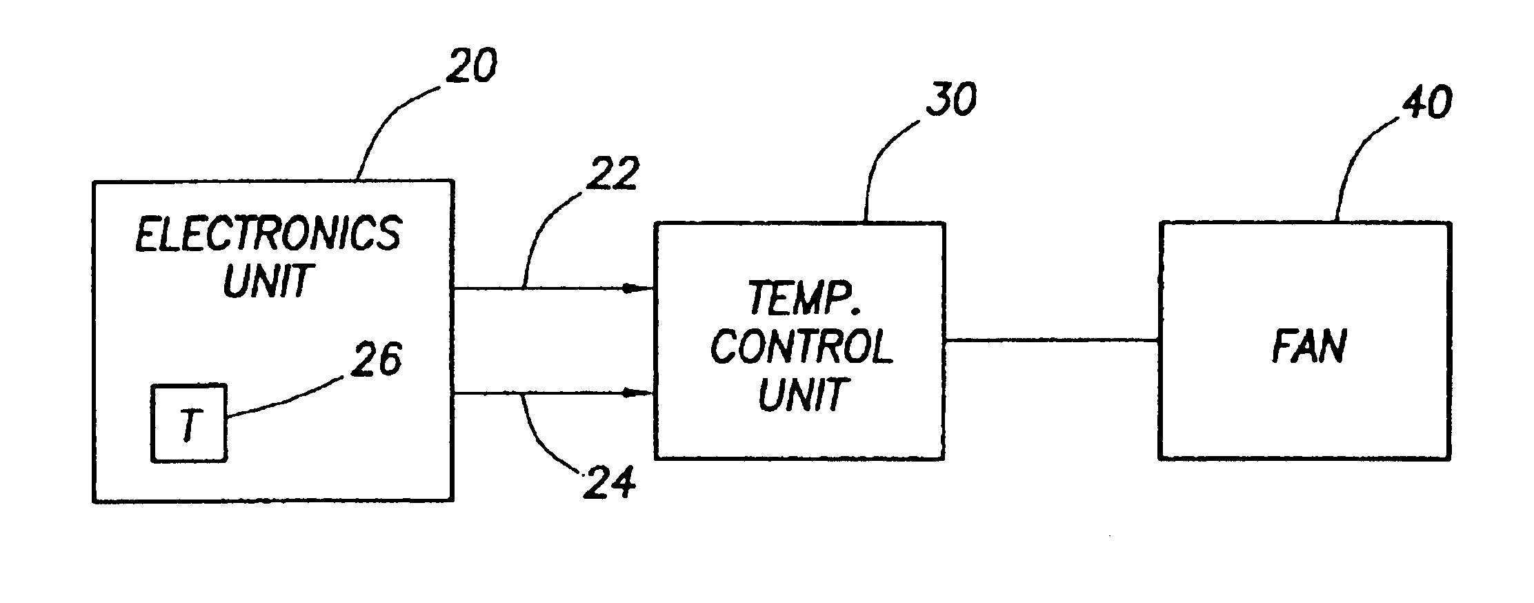
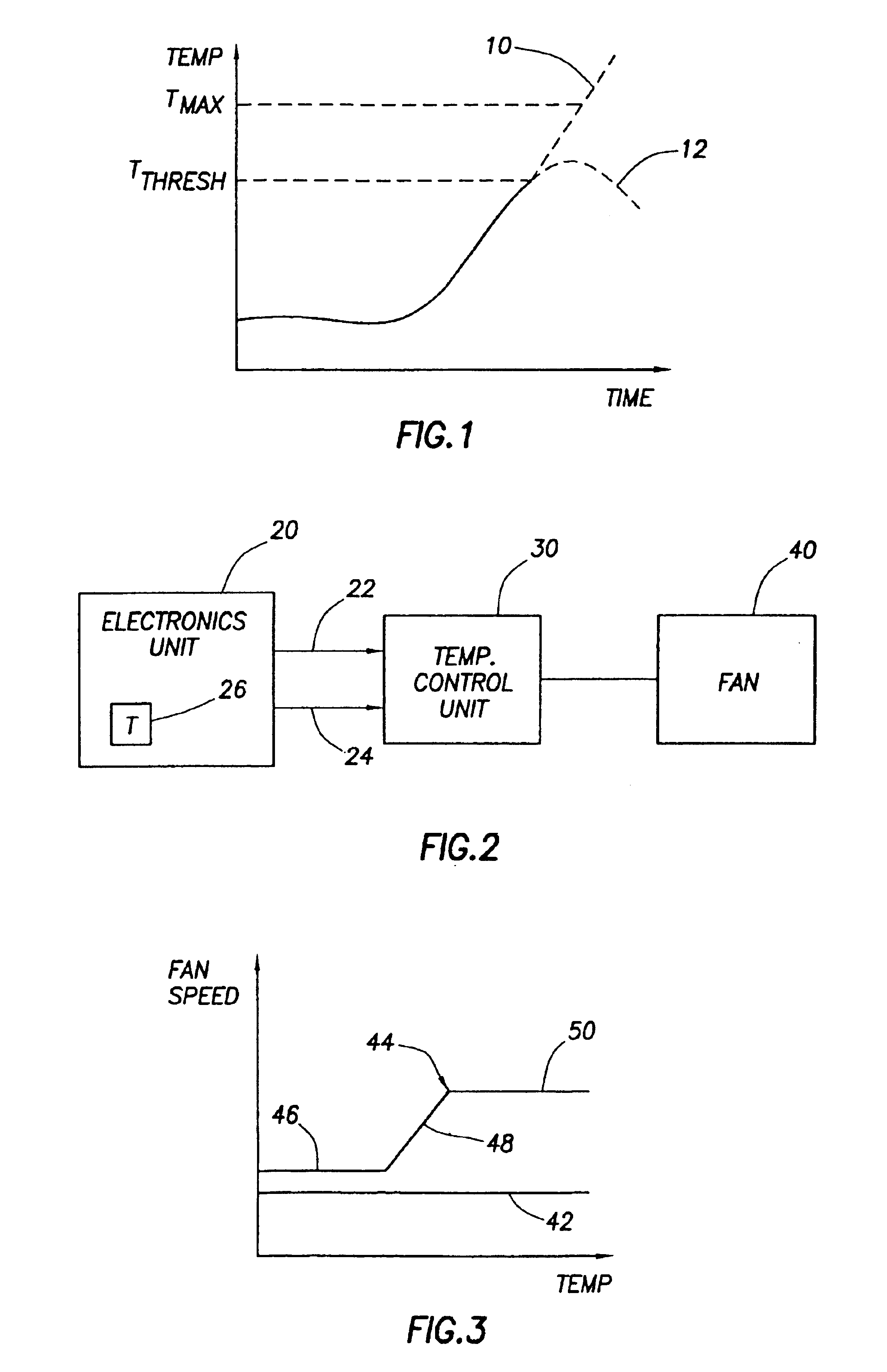
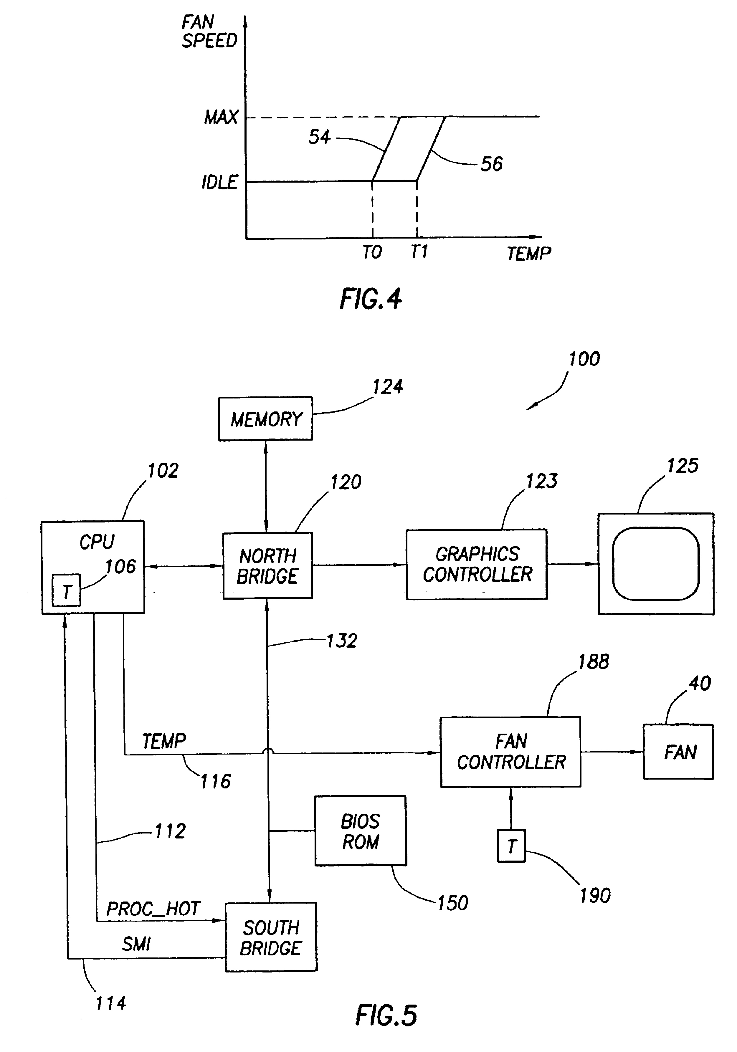
The problems noted above are solved in large part by a temperature control system for an electronics system that tries to minimize fan noise as much as possible. In accordance with the preferred embodiment, the system is capable of implementing a plurality of temperature control protocols. Each protocol generally specifies fan speed as a function of temperature. When the system initializes, a protocol is selected that, on average, is quieter than at least one other protocol, and preferably all other protocols. The system, or a device within the system, monitors its own temperature and, if the temperature reaches or exceeds a threshold, the system causes the initial temperature control protocol to be changed to a different protocol that is better able to cool the system, albeit with a resulting louder sound level. In accordance with one embodiment of the invention, the electronic system comprises a computer having one or more fans that are controlled as described above. If desired, t...


PUM


Abstract

A temperature control system for an electronics system minimizes fan noise as much as possible. The system, which may be a computer, is capable of implementing a plurality of temperature control protocols. Each protocol generally specifies fan speed as a function of temperature. When the system initializes, a protocol is selected that, on average, is quieter than at least one other protocol, and preferably all other protocols. The system monitors its own temperature and, if the temperature reaches a threshold, the system causes the initial temperature control protocol to be changed to a different protocol that is better able to cool the system, albeit with a resulting louder sound level.

Description

CROSS-REFERENCE TO RELATED APPLICATIONSNot applicable.STATEMENT REGARDING FEDERALLY SPONSORED RESEARCH OR DEVELOPMENTNot applicable.BACKGROUND OF THE INVENTION1. Field of the InventionThe present invention generally relates to cooling a computer system. More particularly, the present invention relates to a technique for cooling a computer while reducing fan noise. Still more particularly, the invention relates to the use of throttling capabilities in a computer to dynamically select a thermal solution which is quieter than other thermal solutions.2. Background InformationComputer systems include numerous electrical components that draw electrical current to perform their intended functions. A computer's microprocessor or central processing unit (“CPU”) requires electrical current to perform many functions such as controlling the overall operations of the computer system and performing various numerical calculations. Any electrical device through which electrical current flows produc...

Claims


Application Information

Patent Timeline
Patent Type & Authority Patents(United States)
IPC IPC(8): G05D23/19
CPCG05D23/1912
Inventor ZIARNIK, GREGORY P.
Owner TELEFON AB LM ERICSSON (PUBL)
Learn More