

Method and apparatus for evaluating and calibrating a signaling system
a signaling system and measurement method technology, applied in the field of insitu testing of communications systems, can solve the problems of difficult to observe the fidelity of a signaling system from a transmit circuit to a receive circuit, especially difficult to obtain in-situ measurements of the operation of the system, and measurement derived using external test equipment may not accurately reflect the actual performance of the system under tes
- Summary
- Abstract
- Description
- Claims
- Application Information
AI Technical Summary
Benefits of technology
Problems solved by technology
Method used
Image

Examples
Embodiment Construction
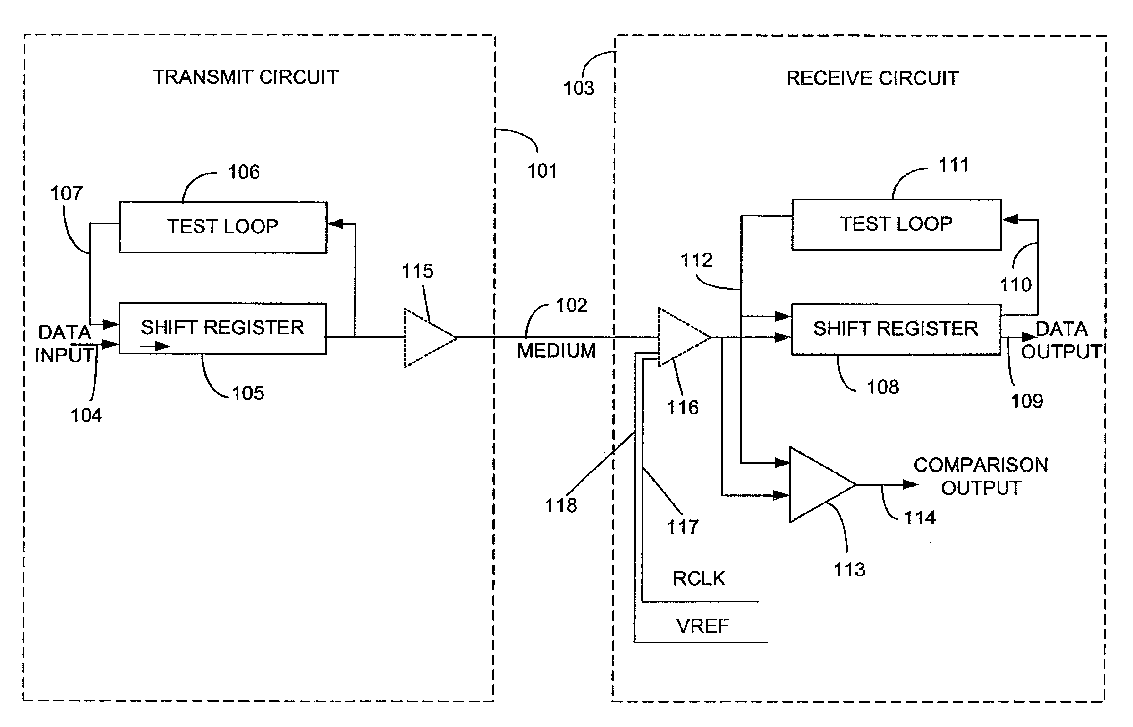
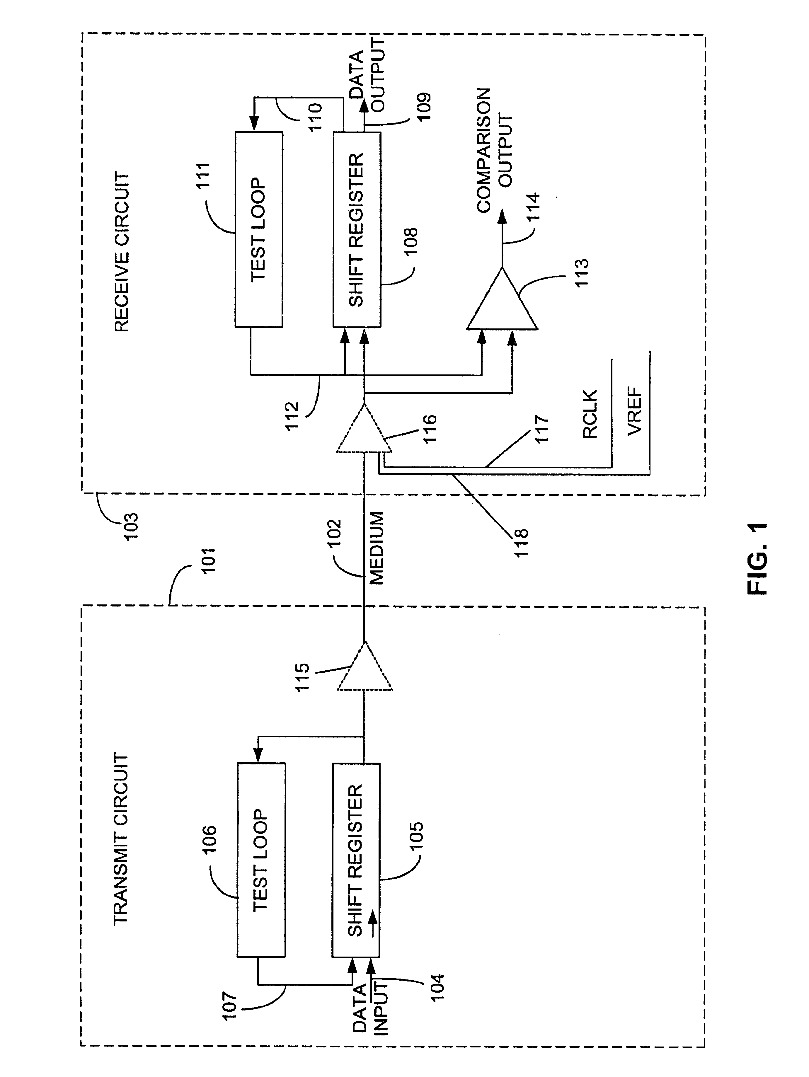
A method and apparatus for evaluating and calibrating a signaling system is described. Evaluation is accomplished using the same circuits actually involved in normal operation of the signaling system. Such circuits are adapted to provide testing capability with minimal additional complexity. Thus, capability for in-situ testing of a signaling system is provided, and information may be obtained from the actual perspective of a receive circuit in the system. Both the need for the introduction of external test equipment and the inaccuracy caused by its introduction are avoided. An embodiment of the invention may be implemented to provide a built-in self-test (BIST) capability within an operational system. Such capability can be very beneficial, especially where access to internal components of a system would otherwise be difficult. For example, in addition to being applicable to signaling systems where the transmit circuit is located separately from the receive circuit, an embodiment o...
PUM
 Abstract
Description
Claims
Application Information