Programmable receiver equalization circuitry and methods

a technology of equalization circuit and programmable receiver, which is applied in the field of digital data communication, can solve the problems of attenuation and phase shift, adversely affecting the performance of a transmission medium, and achieve the effect of reducing high frequency nois

Inactive Publication Date: 2007-01-18
ALTERA CORP
View PDF13 Cites 22 Cited by
  • Summary
  • Abstract
  • Description
  • Claims
  • Application Information

AI Technical Summary

Benefits of technology

[0012] When more than one stage is configured to insert a zero, the frequency ranges in which the stages may insert zeros may be staggered to cover a wide frequency range. When the frequency locations of the zeros are spread out, the slope of the gain provided by the equalization circuit increases across the wide frequency range (i.e., the slope increases by 20 dB/decade at the frequency location of each zero). This allows the frequency response of the ...

Problems solved by technology

Among the characteristics that can adversely affect the per...

Method used


Image

  • Programmable receiver equalization circuitry and methods
  • Programmable receiver equalization circuitry and methods
  • Programmable receiver equalization circuitry and methods

Examples


Embodiment Construction

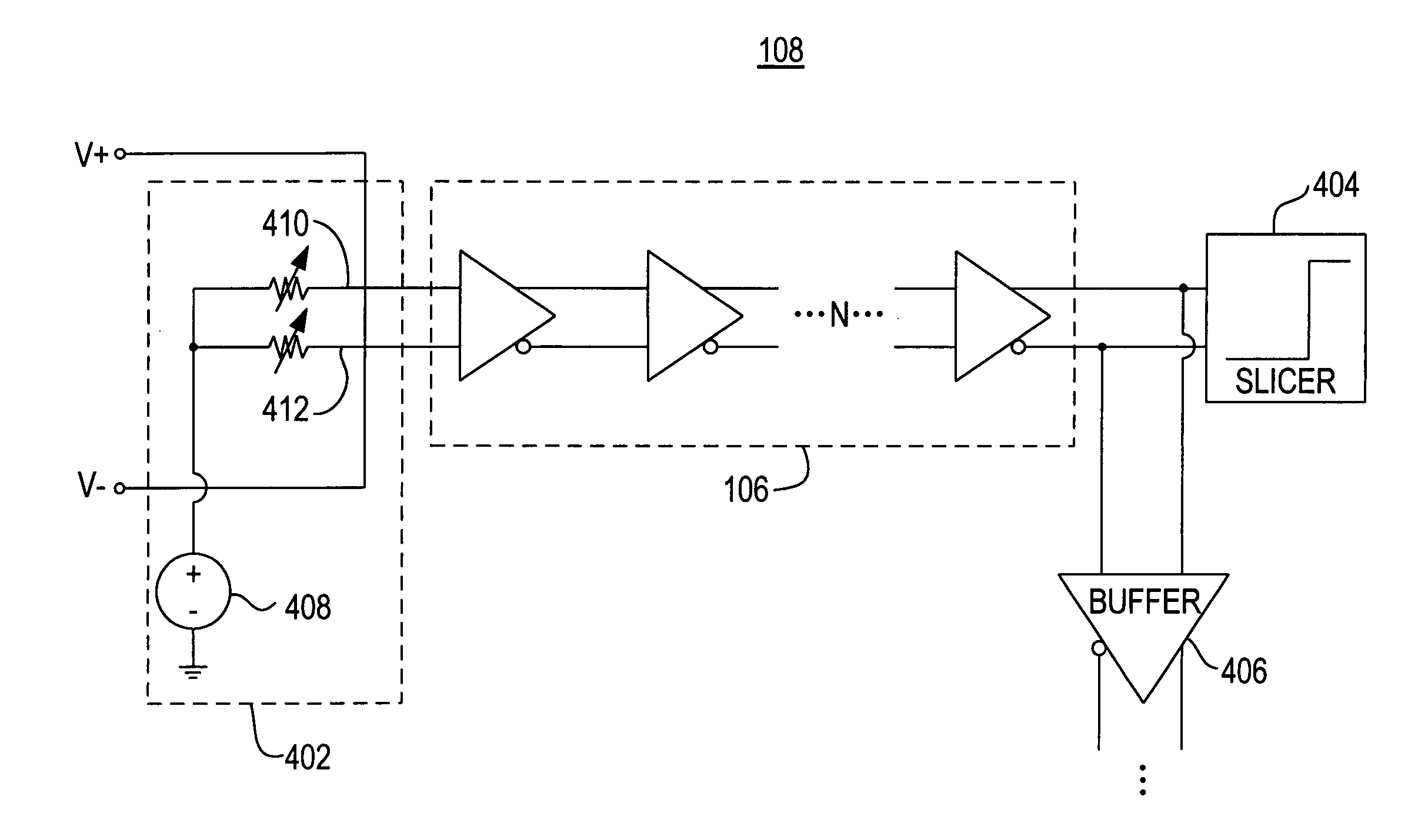
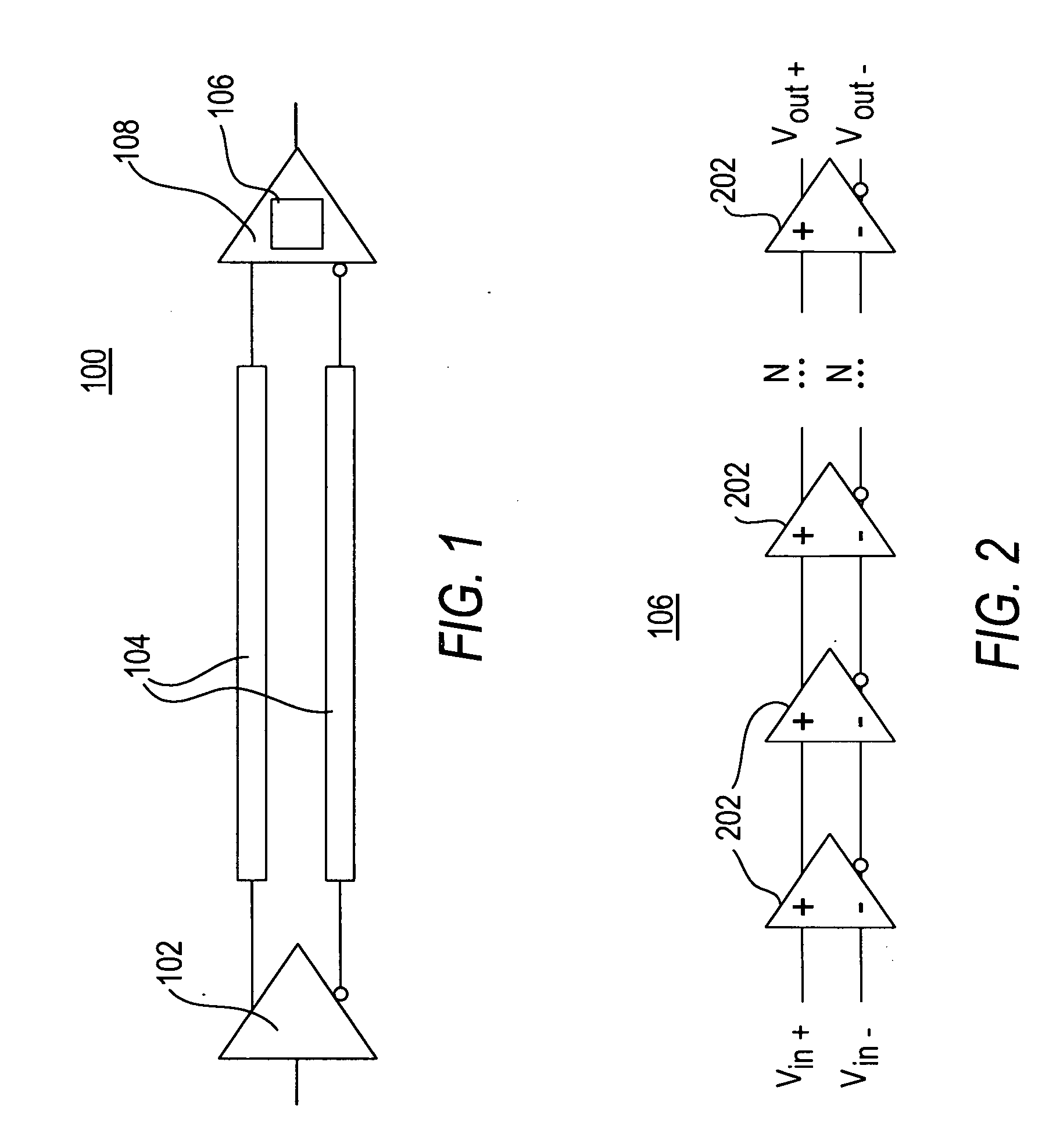
[0021]FIG. 1 is a block diagram of a data transfer system 100 in accordance with the present invention. As shown in FIG. 1, data transfer system 100 includes a driver 102, a transmission medium 104, an equalization circuit 106, and a receiver 108.

[0022] Driver 102 may be part of a device that is configured to transmit data at high data rates. For example, driver 102 may be a component of a programmable logic device, a transceiver, an application-specific integrated circuit (ASIC), or any other suitable device. Driver 102 may employ any suitable serial communications protocol, such as, for example, low-voltage differential signaling (LVDS) in transmitting data. In some embodiments, driver 102 may be tri-statable, which allows multiple drivers (not shown) to be connected to multiple receivers (not shown).

[0023] Transmission medium 104 may carry data transmitted by driver 102 to receiver 108. Transmission medium 104 may be any suitable medium, such as, for example, a printed circuit ...


PUM


Abstract

Data signals transmitted over transmission media suffer from attenuation caused by the transmission media. Equalization circuitry may be provided to compensate for attenuation caused by the transmission media. Equalization circuitry may include multiple stages arranged in series to allow the frequency responses of the stages to aggregate together. Each stage may be programmable to insert a zero, which causes the frequency response of the stage to increase in magnitude by 20 dB/decade. The frequency location of the zero may also be programmable to allow each stage to contribute a certain amount of gain for a specific frequency. Each stage may also be programmable to determine the location of poles for reduction of high frequency noise and cross-talk cancellation.

Description

BACKGROUND OF THE INVENTION [0001] This invention relates to digital data communication, and more particularly to methods and apparatus for automatically adjusting the circuitry involved in such communication to compensate for losses in a digital data signal transmitted from driver circuitry to receiver circuitry. [0002] Different signal transmission media tend to have different signal transmission characteristics. For example, a cable may have a different transmission characteristic than a printed circuit board backplane. In addition, each instance of any given type of transmission medium may have somewhat different characteristics, within a range that is typical for that type of transmission medium. It is also possible for a transmission medium to change over time or as a result of other environmental factors. [0003] Among the characteristics that can adversely affect the performance of a transmission medium are attenuation and phase shift. It is common for the amount of attenuati...

Claims


Application Information

Patent Timeline
IPC IPC(8): H03H7/30
CPCH04B3/04H04L25/03885H04L25/03019
Inventor MAANGAT, SIMARDEEPSHUMARAYEV, SERGEYWONG, WILSONTRAN, THUNGOC
Owner ALTERA CORP
Why Eureka
Try Eureka