Fan control system with improved temperature resolution

a control system and temperature resolution technology, applied in the direction of dynamo-electric converter control, domestic cooling apparatus, instruments, etc., can solve the problem of limiting fine adjustments of pwm signals, bursting of fan speed that produces loud and annoying noises, and the need for complex management schemes in the management of fan operation

Active Publication Date: 2005-04-05
MICROCHIP TECH INC
View PDF24 Cites 32 Cited by
  • Summary
  • Abstract
  • Description
  • Claims
  • Application Information

AI Technical Summary

Problems solved by technology

One problem associated with using signal generators that provide PWM signals to drive fan circuits is that the 8-bit resolution from the temperature sensors for creating the PWM signals limits fine adjustments to the PWM signal when the temperature changes by a very small amount.
The lack of fine adjustment to the PWM signal causes the fan to make undesirably large fan speed adjustments when only a small adjustment would suffice, thereby causing bursts of fan speed that produce loud and annoying noises when the PWM signal is adjusted.
Another problem associated with using signal generators that provide PWM signals to drive fan circuits is that multiple cooling zones create the need for multiple sensors and multiple fans, thereby causing the need for complex management schemes in fan operation management.

Method used


Image

  • Fan control system with improved temperature resolution
  • Fan control system with improved temperature resolution
  • Fan control system with improved temperature resolution

Examples


Embodiment Construction

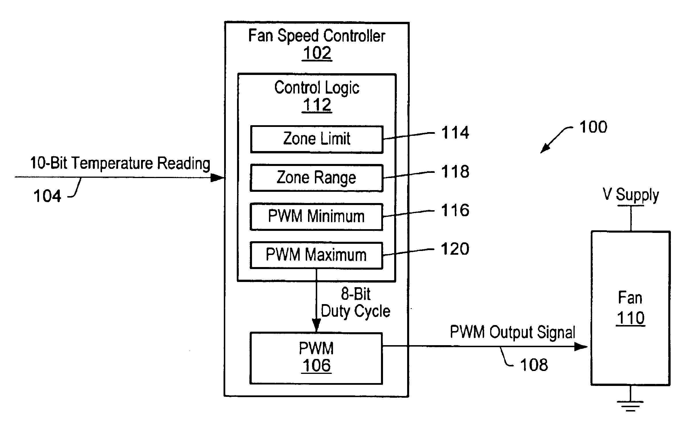
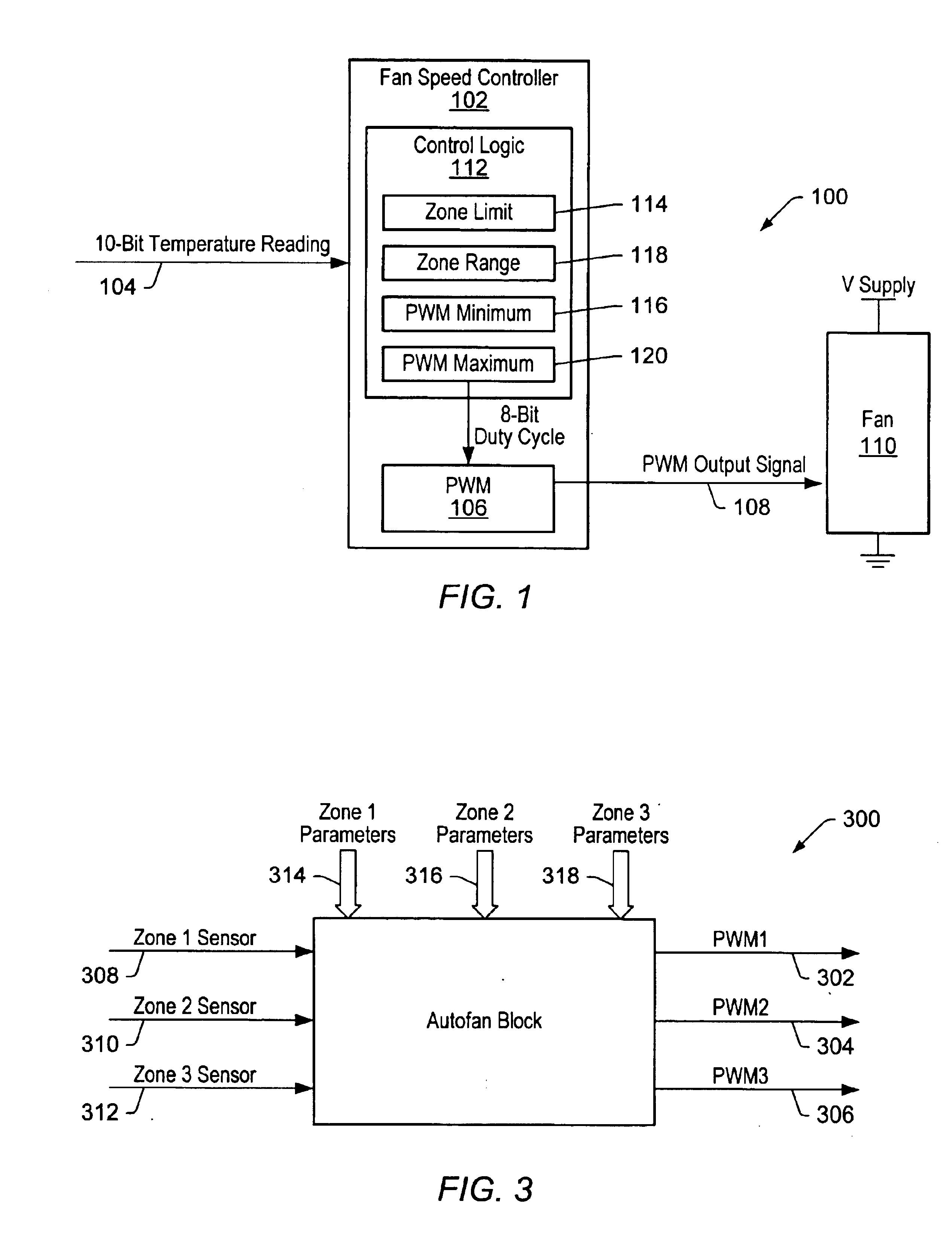
Fan speed control systems often control a fan with a PWM (pulse width modulated) signal generated by a PWM signal generator. The signal generator receives PWM signal parameters for calculation of the PWM signal at a particular time. One of the PWM signal parameters is “duty cycle.” The duty cycle of a PWM signal is the ratio of the amount of time that the PWM signal is asserted to being non-asserted. For example, a PWM signal having a 50% duty cycle is understood to be a PWM signal asserted half the time. The greater the PWM duty cycle, the faster the fan operates, and thus, the greater the air movement is in the fan speed control system. For example, a 100% duty cycle produces a PWM signal that powers the fan at a maximum, whereas a 0% duty cycle produces a PWM signal that turns the fan off.

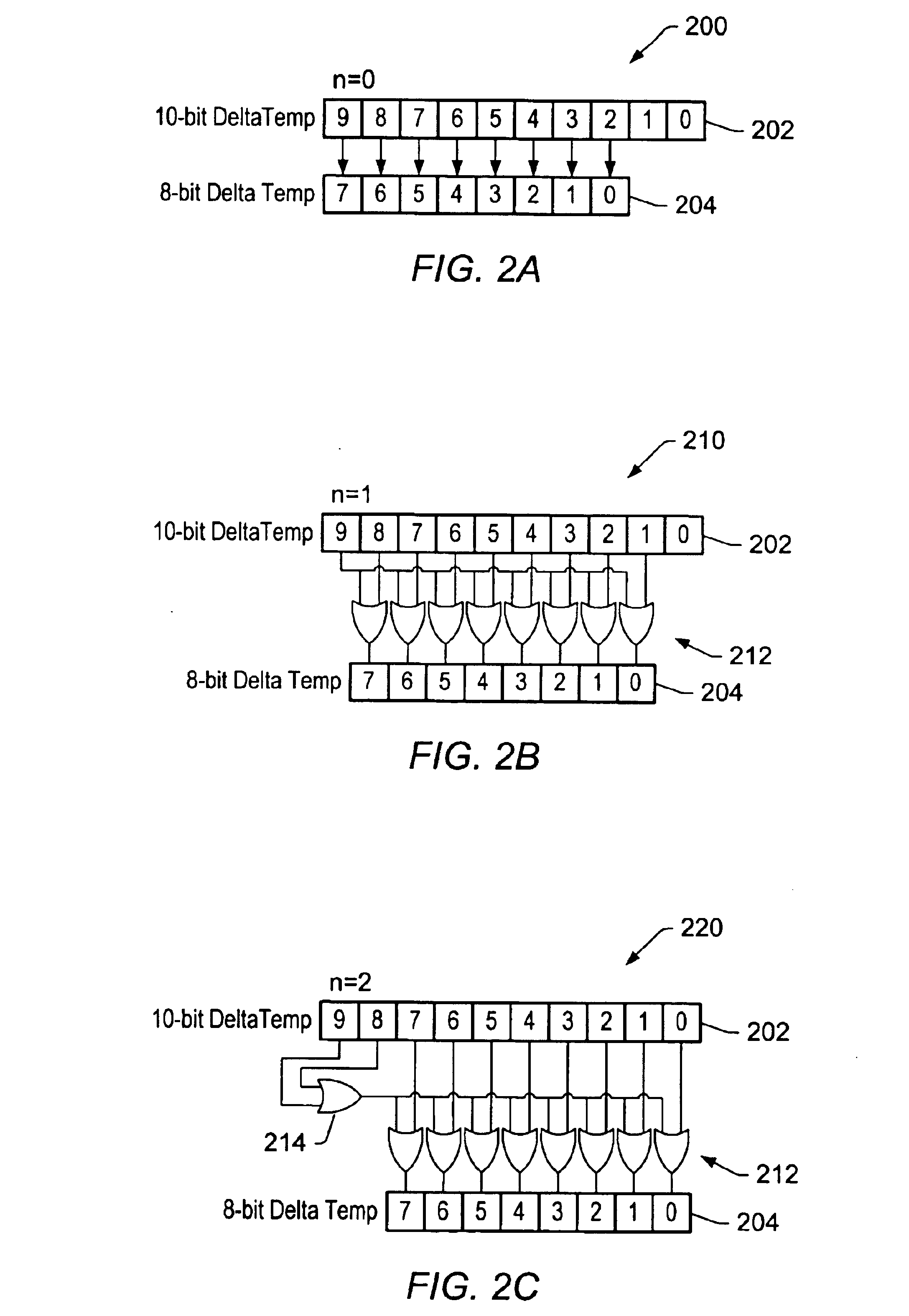
The duty cycle is calculated, in part, from a temperature difference value referred to herein as the “DeltaTemp.” The DeltaTemp value is calculated in various manners depending on the fan speed ...


PUM


Abstract

A system and method for increasing resolution of pulse width modulated (PWM) signal duty cycle calculations in a fan speed control system operating to control rotational speed of at least one fan. The method may comprise obtaining a temperature reading from a first temperature sensor in the fan speed control system during a first time period. The temperature reading has resolution of a first number of bits. A portion of the first number of bits is selected for calculating a PWM signal duty cycle with the resolution of the first number of bits in the temperature reading using only the portion of the first number of bits and zone parameters associated with the first temperature sensor. The PWM signal duty cycle may then be converted into a PWM signal that may be provided to the at least one fan.

Description

BACKGROUND OF THE INVENTION1. Field of the InventionThis invention relates to cooling equipment for electronic systems, e.g., fans, and more particularly, to controlling the rotational speed of a fan.2. Description of the Related ArtFans are often used to evacuate warm air from enclosures in which electronic systems are contained. For example, most computer systems include one or more cooling fans to aid in circulating the air inside the enclosures and for maintaining the temperature inside the enclosures within an acceptable range. The increased airflow provided by fans typically aids in eliminating waste heat that may otherwise build up and adversely affect system operation. Employing cooling fans is especially helpful in ensuring proper operation for certain central processing units (CPUs) with relatively high operating temperatures.Control of fans in a system typically involves a fan control unit executing a fan control algorithm. A fan control algorithm may determine the method...

Claims


Application Information

Patent Timeline
Patent Type & Authority Patents(United States)
IPC IPC(8): F25D17/00G05B5/00H02P1/00H05K7/20
CPCH05K7/20209
Inventor WAHLER, RICHARD E.MARANDO, EILEEN M.BURSTEIN, STEVENMILLER, WAYNE A.
Owner MICROCHIP TECH INC
Why Eureka
Try Eureka