Telescoped multiwall nanotube and manufacture thereof

a nanotube and telescopic technology, applied in the manufacture of electric systems, nickel halides, tube/lamp factory adjustment, etc., can solve the problems of difficult selective contact only of the core tube, the common capped end that seals, and the inability to demonstrate controlled and reversible telescoping of mwnts

Inactive Publication Date: 2005-04-05
RGT UNIV OF CALIFORNIA
View PDF10 Cites 27 Cited by
  • Summary
  • Abstract
  • Description
  • Claims
  • Application Information

AI Technical Summary

Benefits of technology

Accordingly, it is an object of the present invention to overcome the above-mentioned disadvantages of the prior art by providing a method for forming a tel

Problems solved by technology

However, no demonstration of controlled and reversible telescoping of MWNTs has been previously achieved.
A major difficulty in initiating controlled telescoping in MWNTs is the commonly

Method used


Image

  • Telescoped multiwall nanotube and manufacture thereof
  • Telescoped multiwall nanotube and manufacture thereof
  • Telescoped multiwall nanotube and manufacture thereof

Examples


Embodiment Construction

Before the invention is described in detail, it is to be understood that unless otherwise indicated this invention is not limited to particular materials, components or manufacturing processes, as such may vary. It is also to be understood that the terminology used herein is for purposes of describing particular embodiments only, and is not intended to be limiting.

It must be noted that, as used in the specification and the appended claims, the singular forms “a,”“an” and “the” include plural referents unless the context clearly dictates otherwise. Thus, for example, reference to “a nanotube” includes a single nanotube as well as two or more nanotubes, “a shaping electrode” includes a single shaping electrode as well as an assembly of two or more shaping electrodes, “a layer” may be a single layer or may comprise two or more layers and the like.

In this specification and in the claims that follow, reference will be made to a number of terms that shall be defined to have the following ...


PUM


Abstract

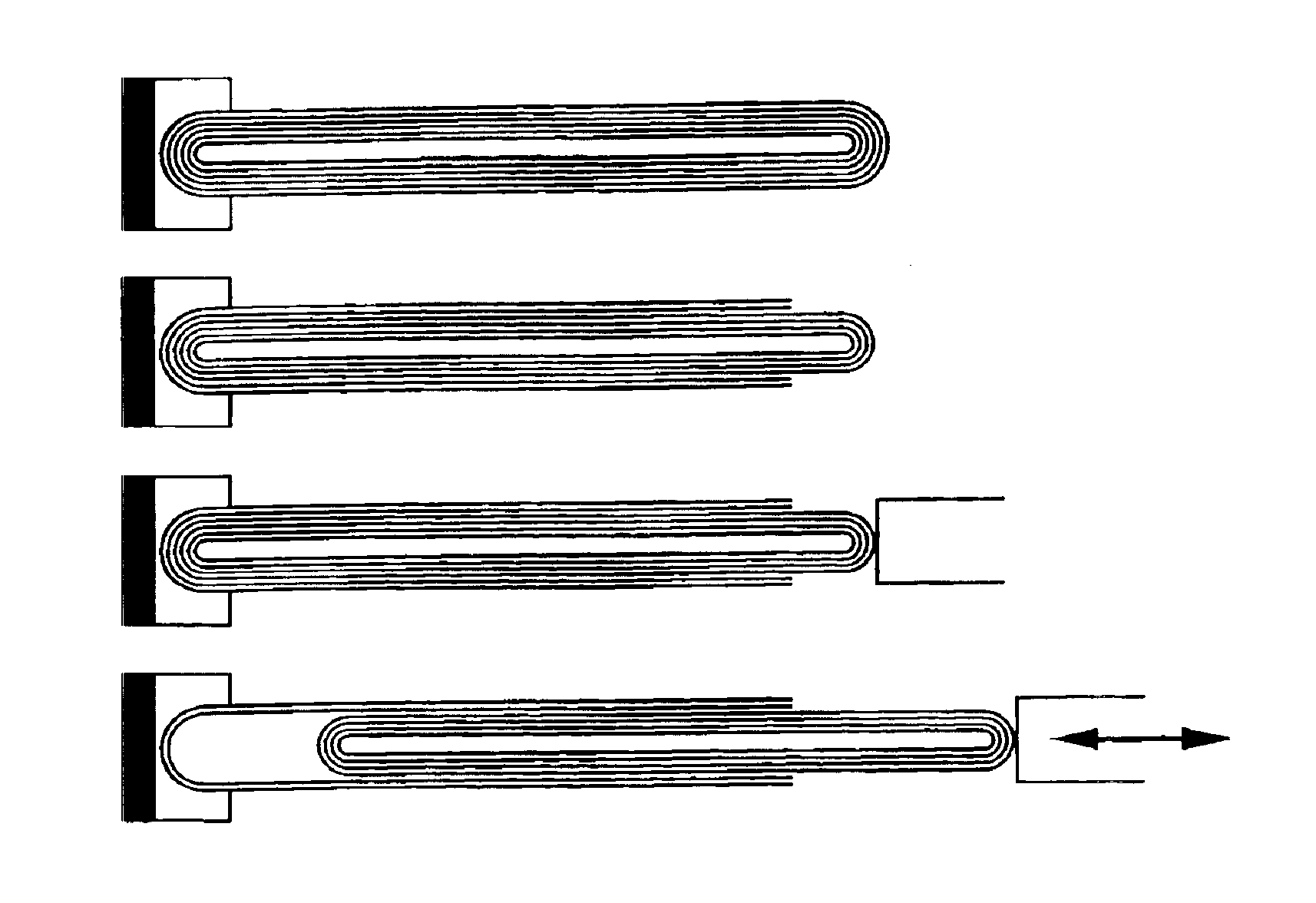
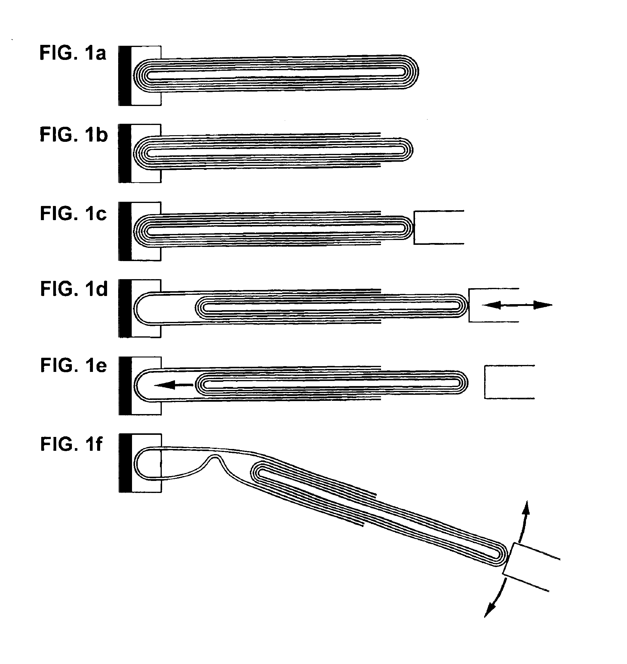
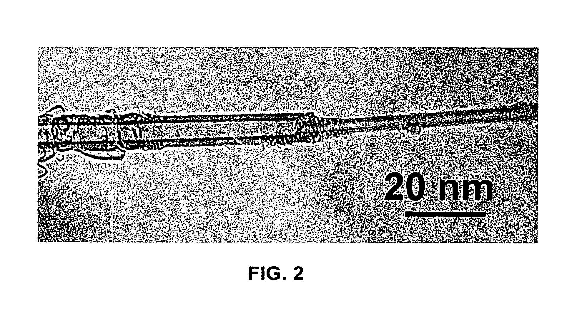
The invention relates to a method for forming a telescoped multiwall nanotube. Such a telescoped multiwall nanotube may find use as a linear or rotational bearing in microelectromechanical systems or may find use as a constant force nanospring. In the method of the invention, a multiwall nanotube is affixed to a solid, conducting substrate at one end. The tip of the free end of the multiwall nanotube is then removed, revealing the intact end of the inner wall. A nanomanipulator is then attached to the intact end, and the intact, core segments of the multiwall nanotube are partially extracted, thereby telescoping out a segment of nanotube.

Description

TECHNICAL FIELDThe present invention relates to a method for forming a low-friction, nanoscale bearings from a multiwall nanotube. The invention finds utility in the field of microelectromechanical systems (MEMS) technology.BACKGROUNDThere is currently substantial interest in reducing the size scale of various mechanical systems, and dramatic recent advances have been achieved in the fabrication of microelectromechanical systems. A review of current trends in microelectromechanical systems can be found in W. Trimmer, (1997) Micromechanics and MEMS: Classic and Seminal Papers to 1990, IEEE Press, New York. Ultimately, such systems are expected to reach well into the nanometer domain, and hence considerations of the mechanical behavior of materials at the nano- or atomic-scale, including those related to atomic perfection and friction, become critically important.Carbon nanotubes, as discussed in Iijima (1991) Nature 354:56-58, have unique mechanical and electronic properties that mak...

Claims


Application Information

Patent Timeline
IPC IPC(8): C01G23/00C01B31/00C01B31/02C01G33/00C01G23/047C01G30/00C01G53/08C01G41/00C01G53/00C30B23/00C30B33/00C01B19/00C01B21/082
CPCB82Y30/00C01B19/007C01B21/0828C01B31/022C01G23/047C01G30/008C01G33/00C01G33/006C01G41/006C01G53/08C30B23/00C30B33/00B82Y40/00C30B29/605Y10T428/2991C01P2004/04C01P2004/13C01P2004/133C01P2004/51C01P2004/61C01P2004/64C01P2006/12Y10S977/743Y10S977/724Y10S977/734Y10S977/752C01B32/158Y10T225/14Y10T225/21Y10T225/211
Inventor CUMINGS, JOHN P.ZETTL, ALEX K.LOUIE, STEVEN G.COHEN, MARVIN L.
Owner RGT UNIV OF CALIFORNIA
Why Eureka
Try Eureka