
Shaft/roller unit for tracked vehicles

Inactive Publication Date: 2005-04-05
SPLIT SRL
View PDF12 Cites 32 Cited by
  • Summary
  • Abstract
  • Description
  • Claims
  • Application Information

AI Technical Summary

Benefits of technology

This structure achieves the following results: the two half-rollers can be hardened entirely and separately before assembly, which ensures a longer life of the roller, the unit has good resistance to axial stresses without structural complications or increases in size at the ends of the shaft, and it is possible to use annular seals which are arranged in close proximity to the shaft and have small diameters and hence a small friction area and a low sliding speed, so that they can also be used on relatively fast tracked vehicles such as tractors.

Problems solved by technology

When the tracked vehicle is in motion, the rollers rotate with the tracks by friction, with a considerable component of sliding and impact friction due to the discontinuity of the links and to the different relative attitudes of the portions of track formed by the links, which are not generally perfectly aligned.
This leads to considerable wear of the tracks and of the support and guide rollers, further aggravated by the environment in which these machines have to operate which causes loose and highly abrasive earthy material to be carried along and interposed between the tracks and the rollers.
The cost of this is structural complications which greatly increase the cost of the unit, make replacement operations onerous, and in any case are at least partially detrimental with regard to other requirements.

Method used


Image

  • Shaft/roller unit for tracked vehicles
  • Shaft/roller unit for tracked vehicles
  • Shaft/roller unit for tracked vehicles

Examples


Embodiment Construction

For a better understanding of the invention, it is appropriate to examine closely the various technical arrangements which have been adopted up to now.

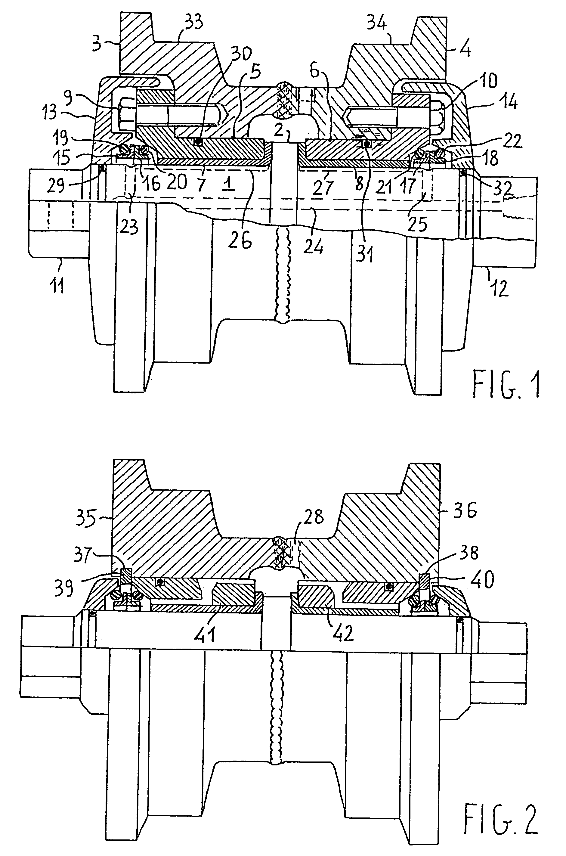
FIG. 1 shows, in a combined front view and diametral section, a shaft / roller unit for tracked vehicles of the prior art.

The unit comprises basically, a cylindrical shaft 1 having an abutment shoulder 2, a pair of half-rollers or rims 3, 4, and a pair of flanged hubs 5, 6.

The two rims, which are arranged reflectively symmetrically in axial alignment with one another, are welded together to form a unitary element, that is, a roller body, shaped generally as an axially hollow reel with the sides recessed to house the flanges of the respective hubs which are housed with their cylindrical portions in the axial cavity of the hollow body.

The two hubs 5, 6 are fitted on the shaft 1, one on each side of the shoulder 2, with the interposition of bushings 7, 8 in the form of flanged cylindrical bushes.

The flanged portions of the two bushin...


PUM


Abstract

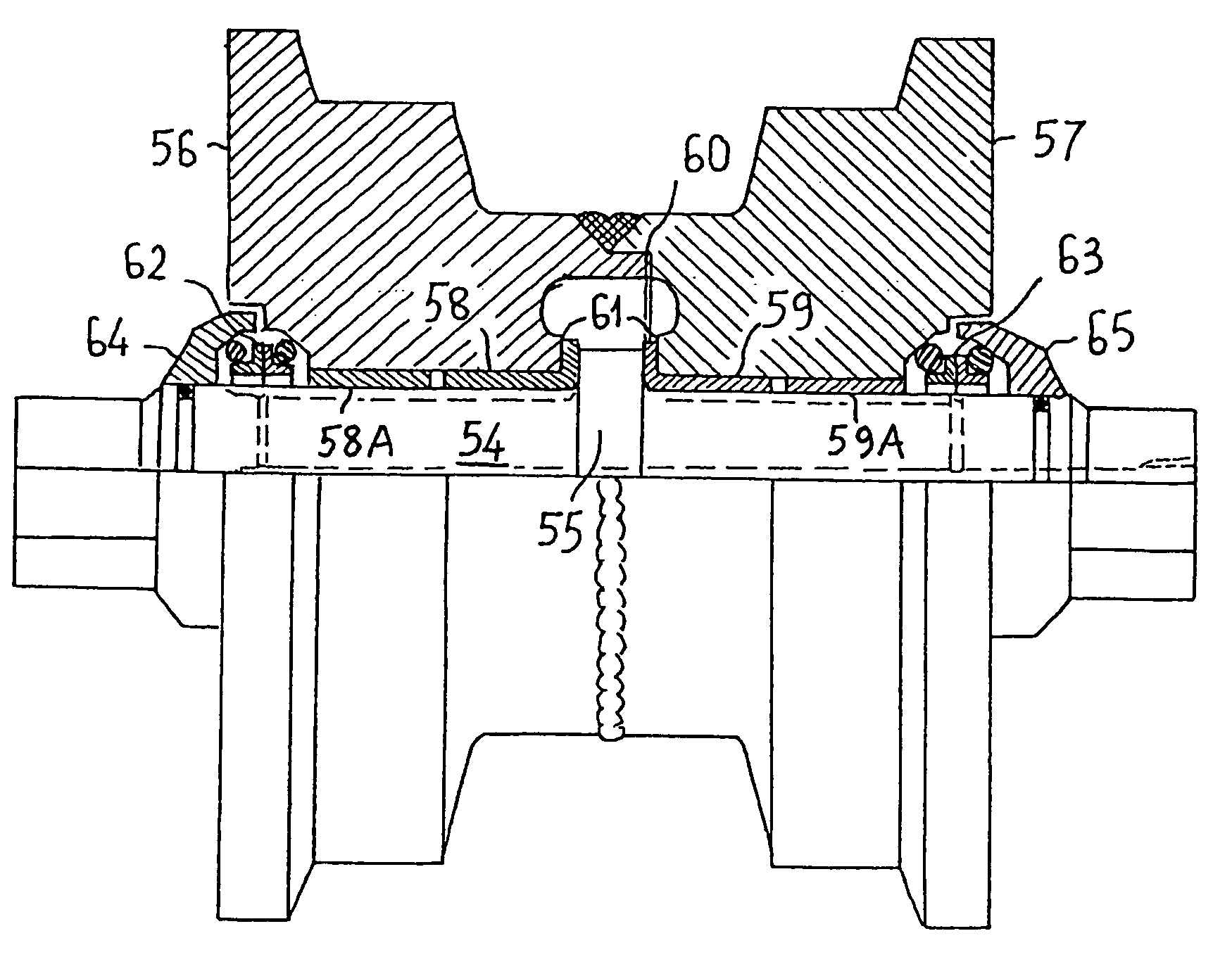
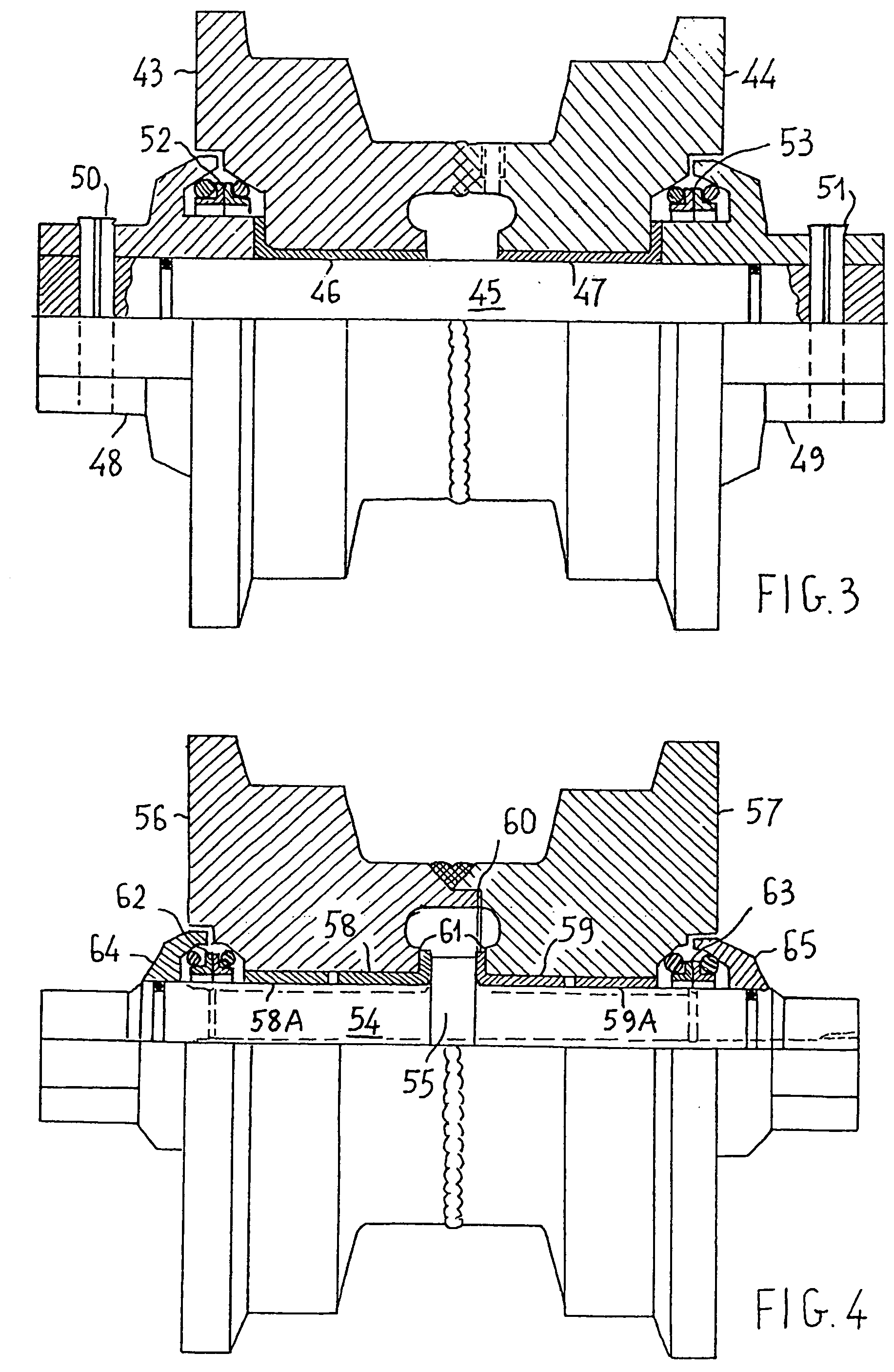
A shaft / roller unit for tracked vehicles which has a long life and resistance to wear is formed by a shaft (54) which has a shoulder (55) in its central portion, perpendicular to its axis, and onto which two wholly hardened steel half-rollers (56, 57) are fitted, one on each side of the shoulder, with the interposition of antifriction bushings (58, 59), the half-rollers grasping the shoulder (55) and, when they have been welded together along a mating contact and locating surface (60), forming a unitary roller which has a predetermined axial position on the shaft and can withstand considerable axial stresses.

Description

FIELD OF THE INVENTION The present invention relates to a shaft / roller unit for tracked vehicles such as tractors, excavators and self-propelled machines in general. BACKGROUND OF THE INVENTION In these machines, the tracks constitute a pair of steering tracks with large surfaces for bearing on the ground, the arrangement of which on the ground is changed by the operation of toothed drive wheels which engage the tracks, whilst the weight of the vehicle, which is often considerable, is supported by lower support rollers which are free to rotate on upper sides or running surfaces of the portions of the tracks which are bearing on the ground. Further, upper rollers, on the other hand, have the function of guiding the return portions of the tracks which are not bearing on the ground. When the tracked vehicle is in motion, the rollers rotate with the tracks by friction, with a considerable component of sliding and impact friction due to the discontinuity of the links and to the different...

Claims


Application Information

Patent Timeline
IPC IPC(8): B62D55/15B62D55/14
CPCB62D55/15
Inventor DUSE, ENZO
Owner SPLIT SRL
Learn More