Orthopaedic cement mixing and dispensing device

a technology for orthopaedic cement and mixing equipment, which is applied in the direction of mixers, diagnostics, applications, etc., can solve the problems of difficult mixing operation, inefficiency, messy transfer, etc., and achieve the effect of better cutting through cemen

Inactive Publication Date: 2005-04-05
SUMMIT MEDICAL
View PDF18 Cites 33 Cited by
  • Summary
  • Abstract
  • Description
  • Claims
  • Application Information

AI Technical Summary

Benefits of technology

It is preferable that the shaft is arranged to rotate about its own axis and also that its axis of rotation itself rotates around the chambers. The use of a rotational axis mixing mechanism enables cement to be more thoroughly mixed. The blades are better able to cut through cement even when it is fairly solid.

Problems solved by technology

This transfer can be messy and time-consuming and may expose the mixture to more air entrapment.
However, such mixing operation is difficult and inefficient and does not guarantee thorough mixing of the cement.
Partial strokes of the ‘masher’ can lead to areas of unmixed powder and the mixing is not consistent, and is reliant on the consistency of the user.
Another problem with the ‘masher’ type system is that it is difficult to mix standard viscosity cement using this plunger.
As the plate is pushed down into the cement, it meets a high resistance, which can result in only a partial mixing stroke being carried out and the cement being compacted at the base of the mixing chamber.
This means that generally the body of the syringe or the mixing chamber is, in fact, much larger than necessary for other types of cement, and requires a longer mixing stroke than would be required for the other low volume cements.
However, with the syringe-type mixers, it is generally not possible to merely increase the dimensions of the mixing chamber, to allow more cement to be mixed.
Increasing the height of the mixing chamber to accommodate the larger quantity of cement is not feasible, as this results in a device which is just too big to handle comfortably.
The longer the chamber is, the more difficult it becomes to introduce the mixing paddle through the column in a correct alignment and to locate the paddle correctly.
This is particularly so when the cement becomes more dense and it becomes extremely difficult to push the paddle down and to cause effective mixing.
However, this device relies on the use of low viscosity cement which, as mixed, falls, under gravity, into the syringe body mixing chamber.
A problem is that unmixed powder can be left in the funnel as the cement reduces, which does not fall into the syringe body mixing chamber.
This can result in the unmixed powder falling into the mixed cement as the funnel part is removed, resulting in dry or dead spots and, thus, a brittle cement.
Another problem is that when mixing standard cements or where mixing is not started straight away, the doughing-up cement can stick to the walls of the funnel and the paddle causing high wastage.

Method used


Image

  • Orthopaedic cement mixing and dispensing device
  • Orthopaedic cement mixing and dispensing device
  • Orthopaedic cement mixing and dispensing device

Examples


Embodiment Construction

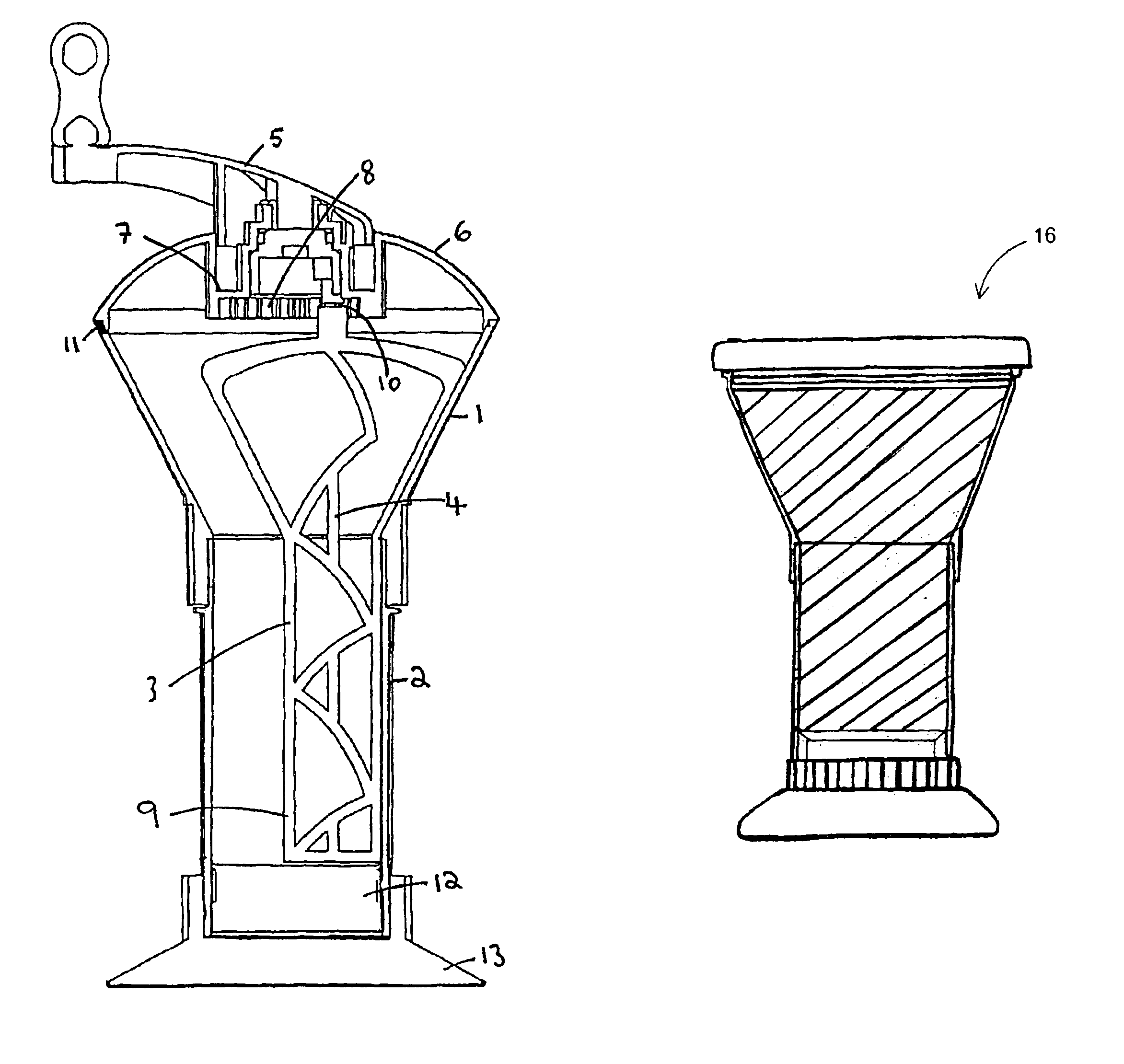
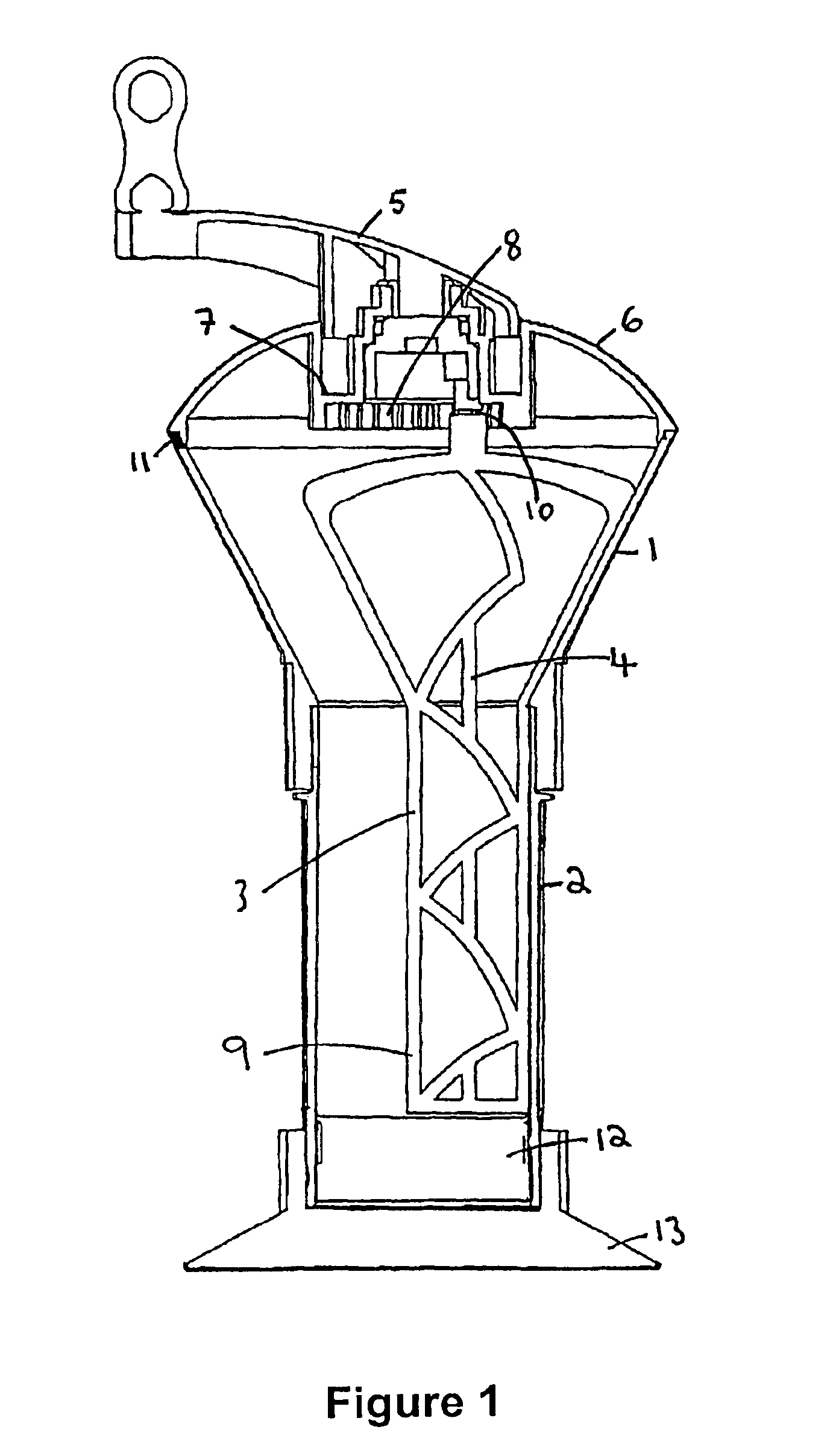
The mixing apparatus comprises a first funnel chamber 1 and a second, cylindrical mixing chamber 2. A mixing paddle 3 extends through both chambers comprising at least one blade supported by a rotatable shaft 4. The shaft, and, therefore, the mixing paddle, is rotated by means of a handle 5. The handle is mounted in a lid 6 adapted to be sealingly fitted onto the top of the funnel 1. A gear mechanism 7 is provided to cause rotation of the shaft 4 about its own axis, as well as rotation of the shaft axis around the mixing chambers.

The preferred gear mechanism comprises a fixed, circular, toothed rack 8 arranged coaxially with respect to the rotation axis of the handle 5, and provided on the underside of the lid 6. The mixing paddle 3 comprises radially extending mixing blades 9, mounted on the shaft 4. The shaft 4 is rotatably mounted, at one end, into the handle 5. A cog-wheel 10 is fixedly attached to the upper part of the shaft 4 for intermeshing engagement with the toothed rack 8...


PUM


Abstract

The apparatus is a mixing and dispensing device for orthopaedic bone cement, comprising an introducer funnel and a mixing syringe body. A mixing shaft and paddle arrangement extends through the funnel and mixing chamber, the paddle having a profile matching the shape of the funnel, in the introducer funnel.

Description

BACKGROUND OF THE INVENTIONThe present invention relates to a device for mixing and delivering orthopaedic bone cement or the like.Orthopaedic bone cement is used throughout the world to secure hip, knee and other anatomic prostheses in an appropriate anatomical position. The bone cement is produced by thoroughly mixing together two components, usually methylmethacrylate monomer liquid and polymethylmethacrylate powder. The mixing was previously carried out using a simple bowl and spatula. The surgeon then removes the required amount of cement and manipulates it by hand before inserting it into a preformed cavity or applying it to a resected bony surface where the prosthesis is to be positioned. Cement may either be applied by hand or may be put into a syringe and applied thereby.Several improvements have been made to this mixing arrangement, including providing arrangements for mixing under vacuum, and to improve the mixing efficiency, to result in a homogenous cement material.Seve...

Claims


Application Information

Patent Timeline
Patent Type & Authority Patents(United States)
IPC IPC(8): A61F2/46B01F15/00B01F13/00A61B19/02A61F2/00A61B19/00B01F7/00
CPCB01F7/00583B01F7/30B01F13/002B01F15/00681A61B2019/0218A61B2019/022A61F2002/30561A61F2002/4685B01F2215/0029A61F2250/0071A61B2050/0064A61B2050/0066B01F27/13B01F27/95B01F33/5011B01F35/4111B01F2101/20B01F35/3202
Inventor FOSTER, DAVID R.
Owner SUMMIT MEDICAL
Why Eureka
Try Eureka