Exhaust gas muffler

a technology of exhaust gas muffler and muffler body, which is applied in the direction of combustion air/fuel air treatment, machines/engines, mechanical equipment, etc., can solve the problems of increasing the weight of the exhaust gas muffler, destroying the catalytic converter, and the conventional catalytic converter is susceptible to external influences, etc., and achieves good flow guidance, good deflection of exhaust gases, and high circulation rate of exhaust gases

Active Publication Date: 2008-04-15
ANDREAS STIHL AG & CO KG
View PDF17 Cites 11 Cited by
  • Summary
  • Abstract
  • Description
  • Claims
  • Application Information

AI Technical Summary

Benefits of technology

[0020]The exhaust gases that enter the exhaust gas muffler via the inlet have a temperature of about 500° C. To achieve a further chemical conversion of the exhaust gases, a distinct increase in temperature of about 150K to 200K or more must be achieved. To heat the exhaust gases, it is provided that they circulate at least partially in a reaction zone. Due to the circulation of the exhaust gas flow a heating of the exhaust gases flowing in can be achieved. At the same time, the retention time of the exhaust gases in the reaction zone is increased, so that chemical reactions can take place in the reaction zone and the chemical conversion of the exhaust gases occurs. The circulating flow ensures that the reaction partners and intermediate products present in the exhaust gas are thoroughly mixed, so that a conversion can take place.
[0022]To achieve the circulating flow, a swirl generator is expediently provided that has at least one feed channel that opens tangentially into the reaction zone. By means of the tangentially opening feed channel, a circulating flow is produced in the reaction zone. A plurality of feed channels, in particular four, expediently open in a rotationally symmetrical manner into the reaction zone. A straightforward configuration results if the swirl generator is disposed on the partition. To achieve a good deflection of the exhaust gases in the reaction zone, and to prevent exhaust gases in the reaction zone from mixing with exhaust gases from surrounding regions, it is provided that the reaction zone be delimited by a cylinder that is fixed in position on the partition. The annular flow is in this connection advantageously designed such that the exhaust gases from the inlet first flow along the cylinder wall and are then deflected and then flow back in the interior of the cylinder, in the direction toward the inlet opening, in a direction opposite to the flow along the cylinder wall. Due to the fact that the exhaust gases flow along the cylinder, they are heated thereby. Subsequently flowing-in exhaust gases are heated along the warm cylinder wall. As a result, an introduction of heat to the flowing-in exhaust gases can be achieved. A recirculation takes place due to the flow that is guided along the wall. In this connection, the cylinder is in particular open toward the second chamber.
[0023]The reaction zone is expediently essentially closed off, and at least one inlet opening leads into the reaction zone and at least one discharge opening leads out of the reaction zone. In this connection, the inlet opening and the discharge opening are advantageously offset relative to one another in a direction transverse to the direction of flow in the reaction zone. As a result, a high circulation rate of the exhaust gases in the reaction zone can be achieved, since the exhaust gases cannot flow directly from the inlet opening into the discharge opening. A straightforward configuration of the exhaust gas muffler is achieved if the reaction zone is delimited by two half shells. A good flow guidance, with little pressure loss, can be achieved if the half shells have an at least partially bulged configuration. In order for the exhaust gas muffler to have few individual components, it is provided that one half shell be monolithically formed with the partition. One half shell is advantageously fixed in position on the partition.

Problems solved by technology

Such a catalytic converter leads to an increase in the weight of the exhaust gas muffler, which is a particular drawback in manually-guided implements.
At the same time, conventional catalytic converters are susceptible to external influences, such as, for example, the quality of the fuel used for the internal combustion engine.
The use of the wrong fuel can lead to destruction of the catalytic converter.
Furthermore, the raw materials from which the catalytic converter is made, are rare and expensive.

Method used


Image

  • Exhaust gas muffler
  • Exhaust gas muffler
  • Exhaust gas muffler

Examples


Embodiment Construction

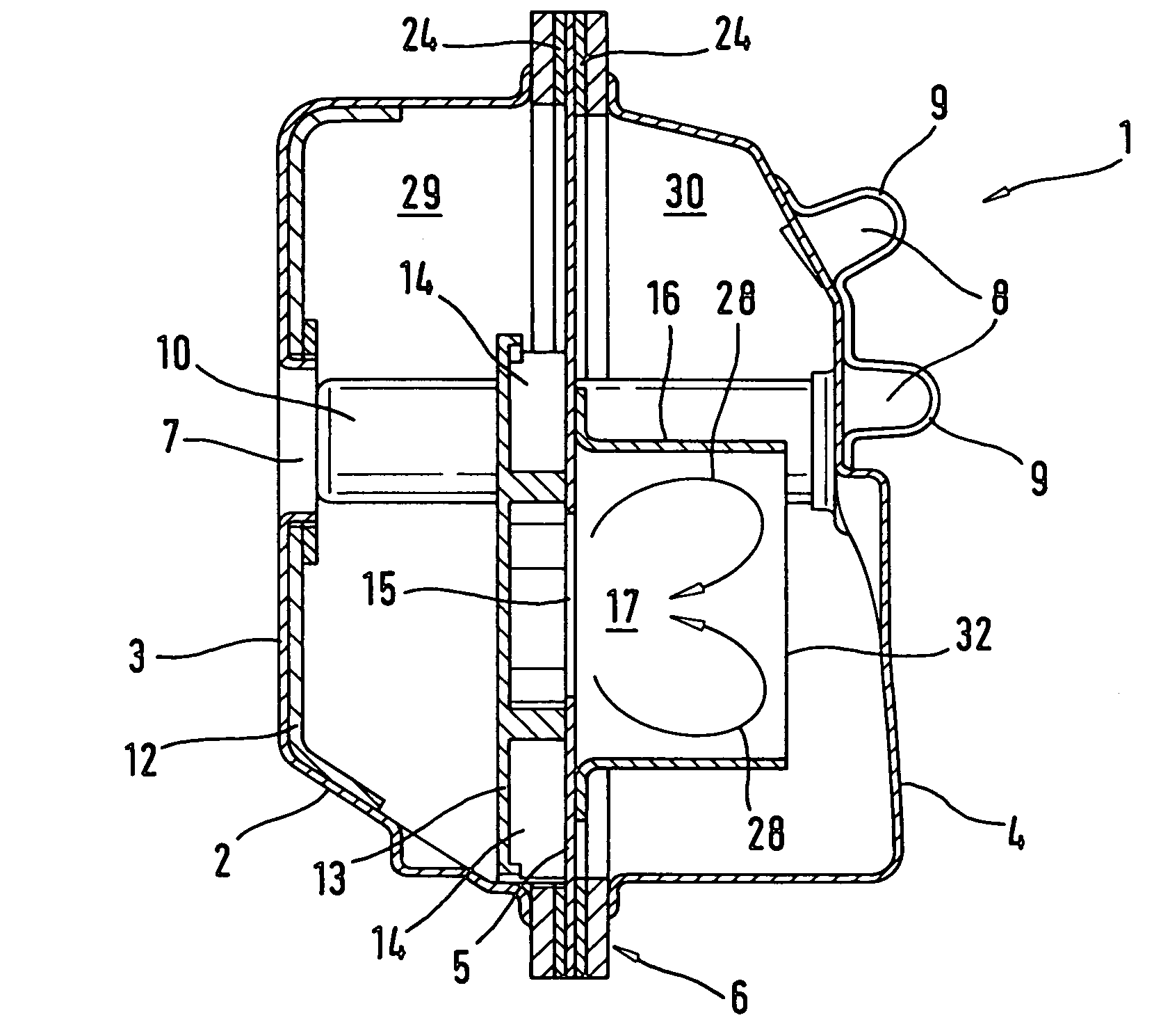
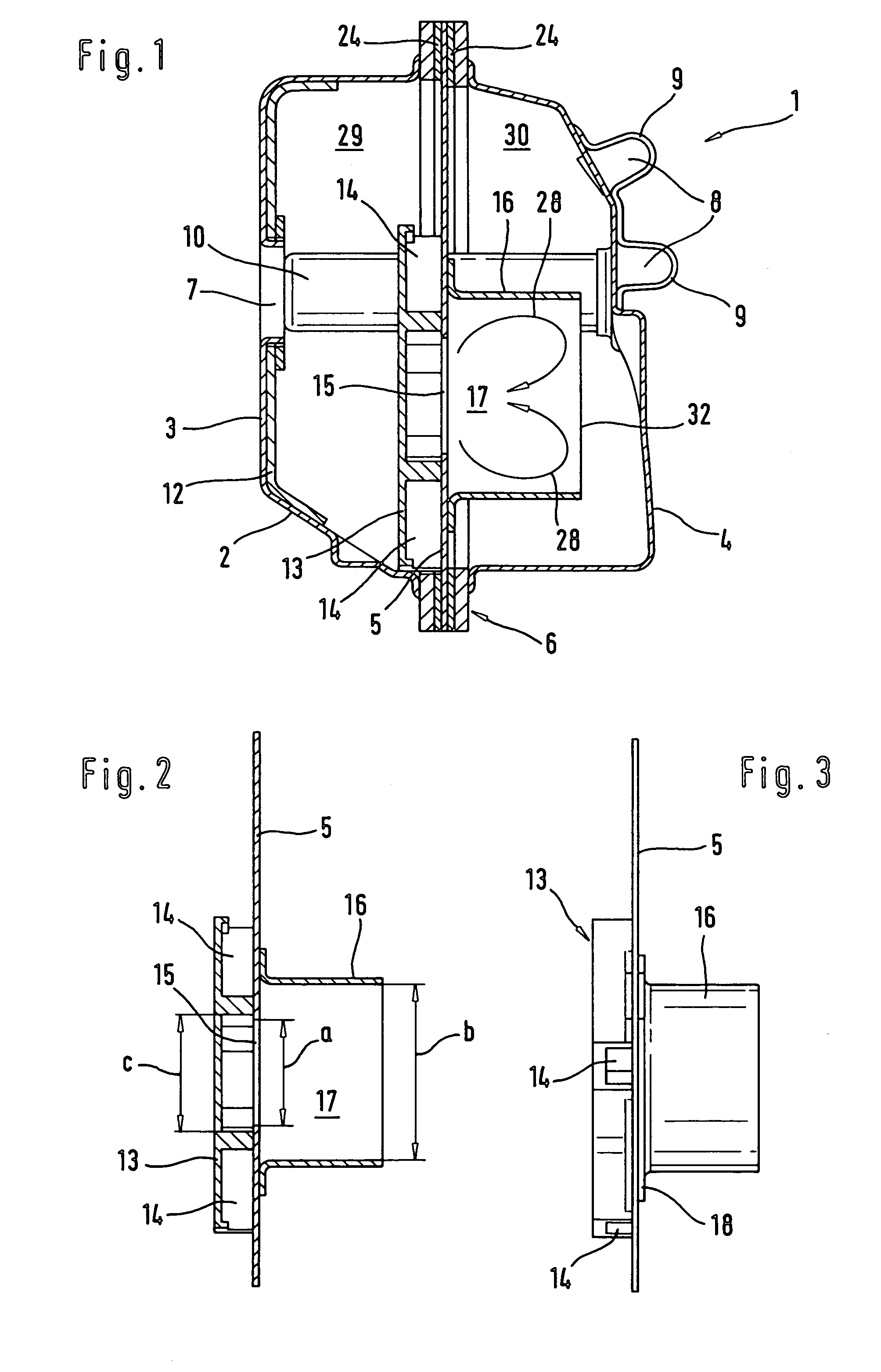
[0027]Referring now to the drawings in detail, the exhaust gas muffler 1, which is illustrated in cross-section in FIG. 1, is provided with a housing 2 that is formed of a lower half 3 and an upper half 4. The two half shells 3, 4 are interconnected at an edge 6. A partition 5 is held at the edge 6 between the two half shells 3, 4. A respective sealing means 24 is disposed on both sides of the partition 5, at the edge 6, between each half shell 3, 4 and the partition 5. However, the edge 6 can also be flanged over without providing a sealing means. The partition 5 separates a first chamber 29 from a second chamber 30. In the lower half 3, the inlet 7 is formed in the housing 2. The outlet 8 leads out of the second chamber 30, and is formed on two hoods 9. At that side facing the internal combustion engine, the lower half 3 is provided with a reinforcing plate 12 for increasing the stability of the exhaust gas muffler 1. The exhaust gas muffler 1 is provided with two sleeves 10 that ...


PUM


Abstract

An exhaust gas muffler is provided for an internal combustion engine, especially for an internal combustion engine in a manually-guided implement such as a power saw, a cut-off machine, or the like. The muffler has a housing having an inlet for exhaust gases and an outlet out of the housing. To achieve an after burning of exhaust gas in a straightforward manner, the exhaust gases in the housing flow through a reaction zone in which the exhaust gases circulate at least partially.

Description

BACKGROUND OF THE INVENTION[0001]The present invention relates to an exhaust gas muffler for an internal combustion engine, especially for the internal combustion engine in a manually-guided implement such as a power saw, a cut-off machine, or the like.[0002]An exhaust gas muffler is disclosed in U.S. Pat. No. 4,890,690. To achieve an adequate exhaust gas quality, a catalytic converter, in which a post treatment of exhaust gas is effected, is disposed in the housing of the exhaust gas muffler between the inlet and the outlet in the direction of flow. Such a catalytic converter leads to an increase in the weight of the exhaust gas muffler, which is a particular drawback in manually-guided implements. At the same time, conventional catalytic converters are susceptible to external influences, such as, for example, the quality of the fuel used for the internal combustion engine. The use of the wrong fuel can lead to destruction of the catalytic converter. Furthermore, the raw materials ...

Claims


Application Information

Patent Timeline
Patent Type & Authority Patents(United States)
IPC IPC(8): F01N7/00F01N1/08F01N3/28F01N13/00F01N13/18
CPCF01N1/086F01N1/088F01N3/2885F01N13/002F01N13/1894F01N2590/06
Inventor MAIER, GEORG
Owner ANDREAS STIHL AG & CO KG
Why Eureka
Try Eureka