
Reaction injection molding assembly for manufacturing a golf ball component

Inactive Publication Date: 2007-03-29
CALLAWAY GOLF CO
View PDF99 Cites 11 Cited by
  • Summary
  • Abstract
  • Description
  • Claims
  • Application Information

AI Technical Summary

Benefits of technology

[0012] The exemplary embodiments disclosed below provide new mold configurations, assemblies and processes which eliminate the occurrence of many types of cosmetic defects otherwise occurring on golf balls.
[0017] One advantage of the exemplary embodiment is that the constituent materials are mixed thoroughly, thereby providing a more consistent intermediate and / or cover layer, resulting in better golf ball performance characteristics.
[0018] Another advantage of the exemplary embodiment is that the use of new, lower viscosity materials may be explored, resulting in enhanced golf ball properties and performance.
[0019] Yet another advantage of the exemplary embodiment is that increased mixing of lower viscosity materials allows the intermediate layer or cover to be thinner, resulting in increased ball performance.
[0020] Still another advantage of the exemplary embodiment is that a unique venting configuration of the mold reduces the porosity of the material being processed, creating a ball cover or other layer that is substantially free from voids.
[0021] A further advantage of the exemplary embodiment relates to the elimination of many forms of cosmetic defects that otherwise occur as a result of conventional molding equipment and techniques.

Problems solved by technology

Some of these materials facilitate processing by compression molding, yet disadvantages have arisen.
These disadvantages include, among others, the presence of seams in the cover, which occur where the pre-sized sections of cover material were joined, and high process cycle times which are required to heat the cover material and complete the molding process.
Injection molding is well-suited for thermoplastic materials, but has limited application to some thermosetting polymers.
However, certain types of these thermosetting polymers often exhibit the hardness and elasticity desired for a golf ball cover.
As a result, traditional injection molding techniques do not provide proper processing when applied to these materials.
Although satisfactory in certain respects, golf balls produced by current molding techniques frequently suffer from a variety of cosmetic defects.

Method used


Image

  • Reaction injection molding assembly for manufacturing a golf ball component
  • Reaction injection molding assembly for manufacturing a golf ball component
  • Reaction injection molding assembly for manufacturing a golf ball component

Examples


Embodiment Construction

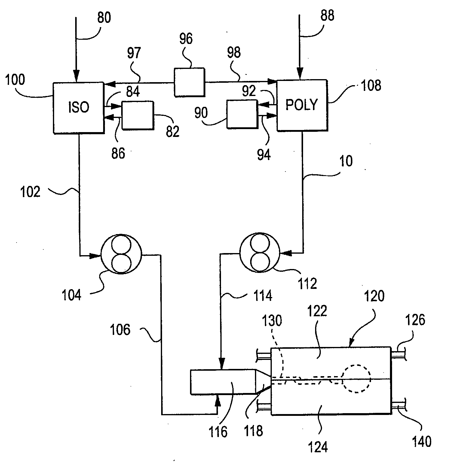
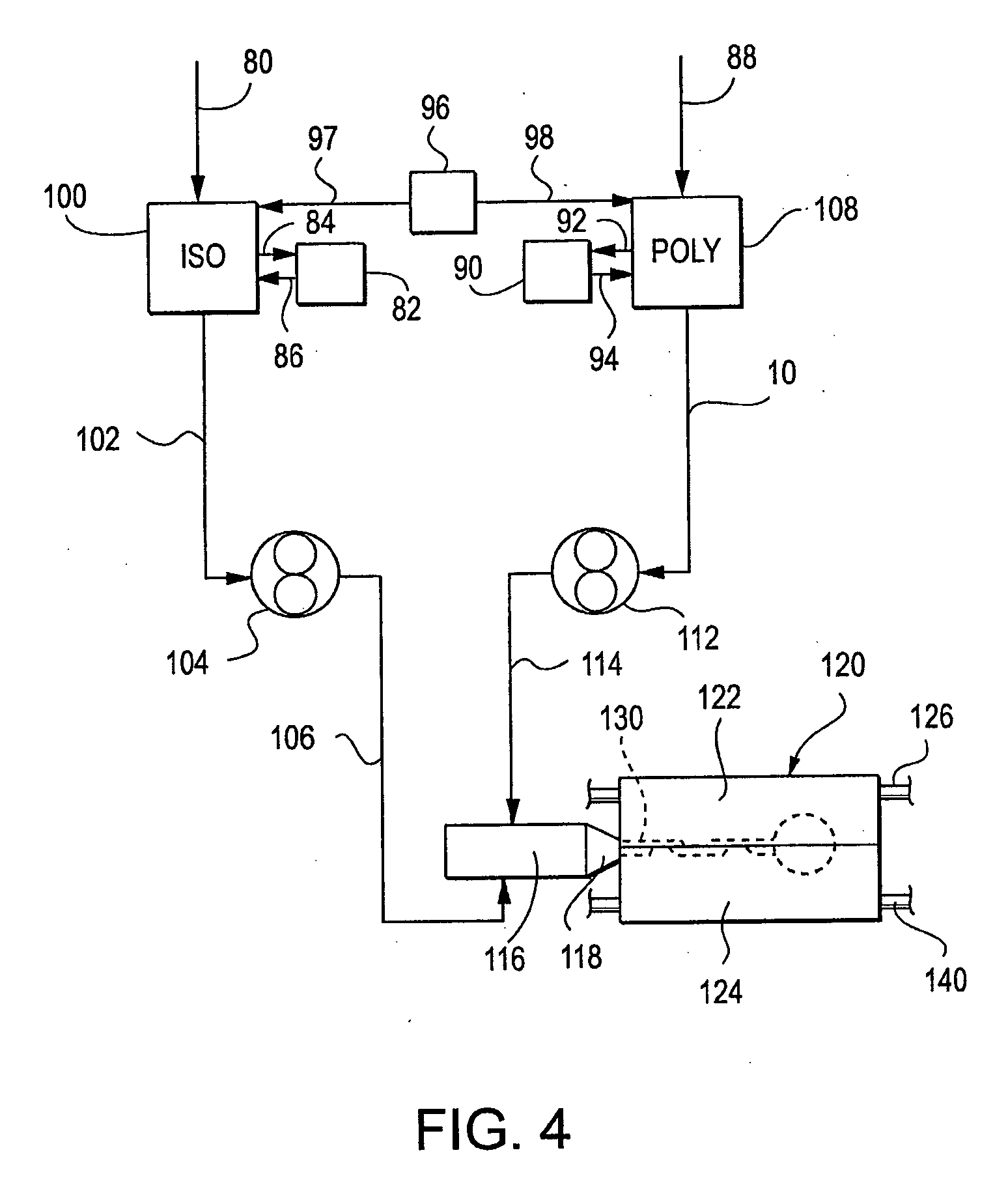
[0045] The exemplary embodiments provide a new mold or die configuration and a new method of processing for reaction injection molding a golf ball cover or inner layer which significantly reduces cosmetic defects and promotes increased mixing of constituent materials, resulting in enhanced properties and the ability to explore the use of materials new to the golf ball art.

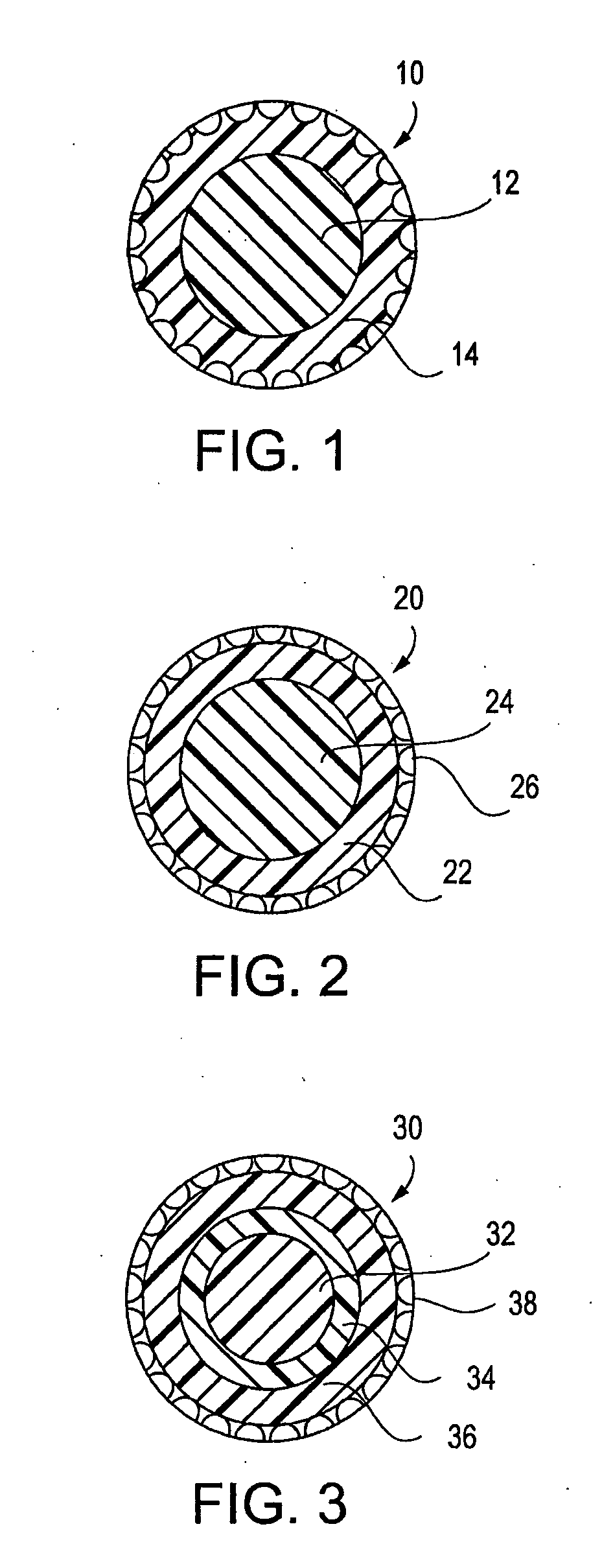
[0046] A preferred embodiment of the exemplary embodiment is a golf ball in which at least one cover or core layer comprises a fast-chemical-reaction-produced component. This component includes at least one material selected from the group consisting of polyurethane, polyurea, polyurethane ionomer, epoxy, and unsaturated polyesters, and preferably comprises polyurethane. The exemplary embodiment also includes a method of producing a golf ball which contains a fast-chemical-reaction-produced component. A golf ball formed according to the exemplary embodiment preferably has a flex modulus in the range of from about ...


PUM

PropertyMeasurementUnit
Angleaaaaaaaaaa
Angleaaaaaaaaaa
Angleaaaaaaaaaa

Abstract

A molding assembly and related process are described that eliminate or significantly reduce cosmetic defects otherwise occurring in golf balls. The assembly includes molds with particular runner configurations, gate configurations, and venting characteristics. The assemblies and processes described herein are particularly well suited for reaction injection molding of golf balls.

Description

CROSS REFERENCES TO RELATED APPLICATIONS [0001] Not Applicable STATEMENT REGARDING FEDERALLY SPONSORED RESEARCH OR DEVELOPMENT [0002] Not Applicable BACKGROUND OF THE INVENTION [0003] 1. Field of the Invention [0004] The present invention relates to manufacturing golf balls. More specifically, the present invention relates to a manufacturing golf balls utilizing reaction injection molding. [0005] 2. Description of the Related Art [0006] Golf balls are typically made today by molding a core of elastomeric or polymeric material into a spheroid shape. A cover is then molded around the core. Sometimes, before the cover is molded about the core, an intermediate layer is molded about the core and the cover is then molded around the intermediate layer. The molding processes used for the cover and the intermediate layer are similar and usually involve either compression molding or injection molding. [0007] More particularly, in compression molding processes, the golf ball core is inserted i...

Claims


Application Information

Patent Timeline
IPC IPC(8): B29C45/14
CPCA63B37/0003A63B45/00B29C67/246B29L2031/545A63B37/0027A63B37/0076A63B37/0037A63B37/0045A63B37/0051A63B37/0074A63B37/0075A63B37/0033B29B7/7471B29B7/7615B29B7/7694
Inventor VEILLEUX, THOMAS A.MELANSON, DAVID M.BERGIN, THOMAS R.
Owner CALLAWAY GOLF CO
Learn More