Slurry mixer outlet

a slurry mixer and outlet technology, applied in the field of slurry mixers, can solve the problems of clogging of the apparatus, difficult adjustment of the flow of slurry, and separation of materials in the mix, so as to prevent the occurrence of mixer or conduit lumps and/or paper breaks, and reduce the occurrence of unwanted premature setting of gypsum

Inactive Publication Date: 2005-04-05
UNITED STATES GYPSUM CO
View PDF27 Cites 232 Cited by
  • Summary
  • Abstract
  • Description
  • Claims
  • Application Information

AI Technical Summary

Benefits of technology

Accordingly, the above-listed objects are met or exceeded by the present apparatus and method for controlling the output of a slurry mixer including the features of eliminating the canister and its undesirable vortex and replacing it with an extended mixing and dispensing apparatus. The extended mixing and dispensing apparatus gate preferably includes an elongate, preferably flexible conduit which provides additional space for uniform mixing of slurry and additives such as foam, retarders, dispersants and accelerators. By providing a flexible mixing chamber in the conduit, unwanted premature setting of the gypsum is prevented so that occurrences of mixer or conduit lumps and / or paper breaks are reduced. Also, coiling of the chamber is available for applications in which there is limited space in the board line between the mixer outlet and the board forming plate. In the latter application, an extended length mixing chamber is provided which is applicable with board lines having limited space.

Problems solved by technology

The discharge gate controls the flow of slurry from the mixer, and is difficult to adjust to change slurry flow when product requirements change, such as when thicker or thinner wallboard is desired.
One drawback of such canisters is that a centrifugal force set up within the canister causes separation between the materials in the mix due to density differences.
More specifically, recent studies have shown that a vortex is created as the mixture flows in the canister, which also creates an empty air space in the canister.
Such an air space is typically representative of unwanted buildup of material in the canister, which then more easily sets and causes clogging of the apparatus.
Clogged mixing equipment causes costly downtime for repairs.
Another disadvantage of the vortex created in the canister is that higher density slurry components become separated from the relatively lower density foam.
If the pressure of the dispensed slurry is too high, the previously deposited layer is disturbed, resulting in a condition known as “washout”.

Method used


Image

  • Slurry mixer outlet
  • Slurry mixer outlet
  • Slurry mixer outlet

Examples


Embodiment Construction

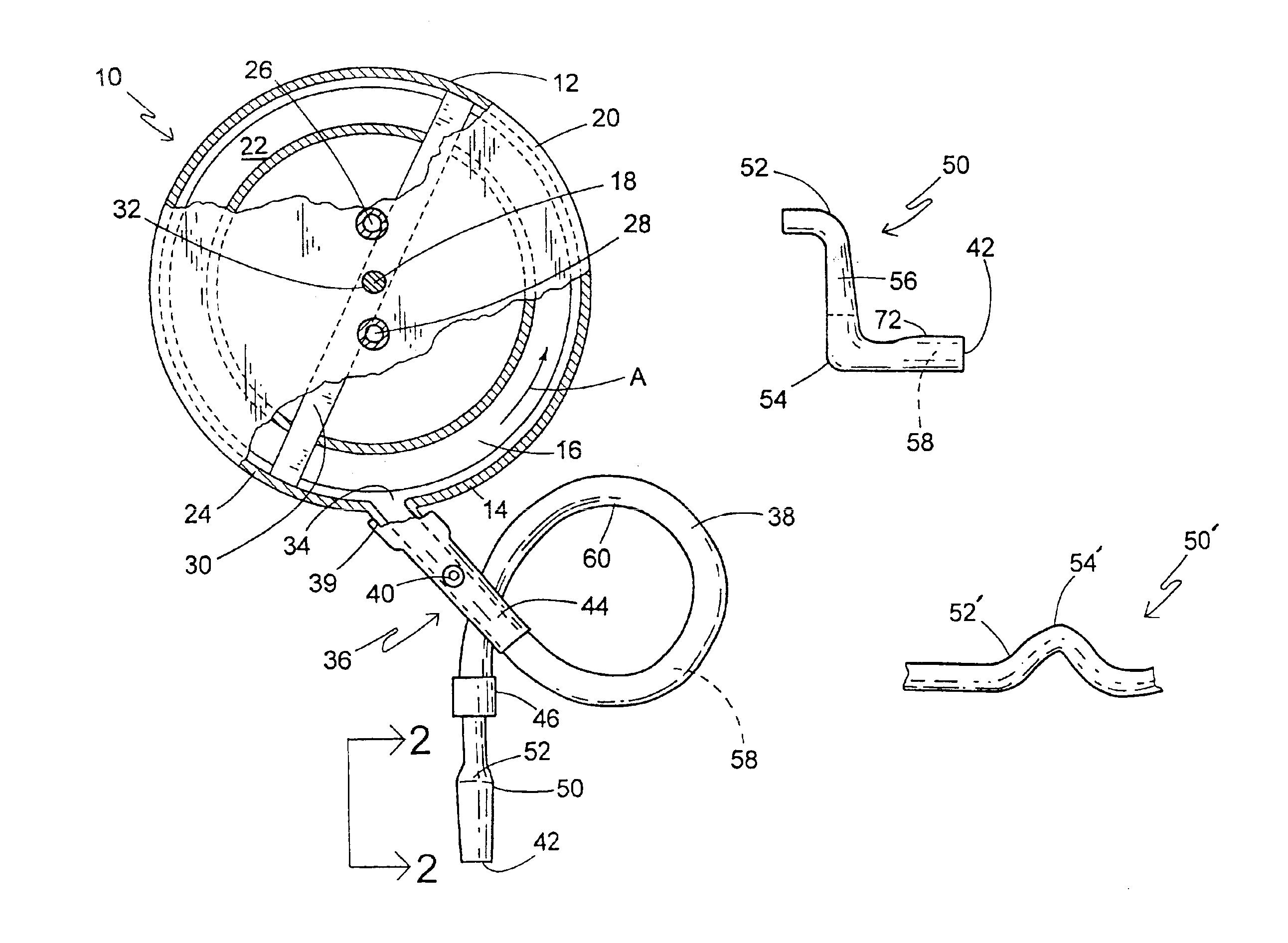
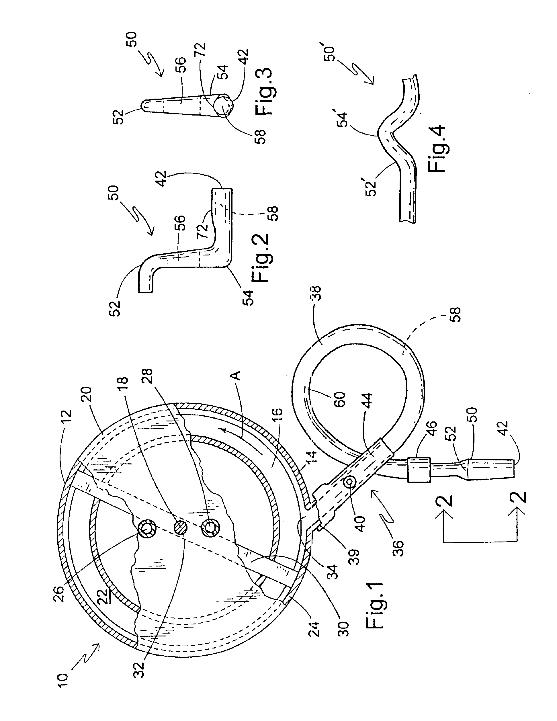
Referring now to FIG. 1, a mixing apparatus for mixing and dispensing a slurry is generally designated 10 and includes a mixer 12 having a housing 14 configured for receiving and mixing the slurry. The housing 14 defines a mixing chamber 16 which is preferably generally cylindrical in shape, has a generally vertical axis 18, and upper radial wall 20, a lower radial wall 22 and an annular peripheral wall 24. An inlet 26 for calcined gypsum and an inlet 28 for water are both positioned the upper radial wall 20 proximate the vertical axis 18. It should be appreciated that the inlets 26, 28 are connected to gypsum and water supply containers respectively (not shown), such that gypsum and water can be supplied to the mixing chamber 16 by simple gravity feed. Also, as is well known in the art, other materials or additives in addition to gypsum and water, often employed in slurries to prepare gypsum products (e.g. accelerators, retarders, fillers, starch, binders, strengtheners, etc.) can ...


PUM

PropertyMeasurementUnit
diameteraaaaaaaaaa
lengthaaaaaaaaaa
inner diameteraaaaaaaaaa

Abstract

An apparatus configured for connection to a mixer for receiving a slurry and altering the flow characteristics of the slurry includes a conduit having a main inlet in slurry receiving communication with the mixer outlet and extending to a spout for discharging the slurry, at least one conduit restrictor associated with the conduit for creating back-pressure between the conduit restrictor and the mixer outlet for keeping the mixer full, and at least one pressure reducer associated with the discharge spout and configured for reducing the pressure of the slurry dispensed from the discharge spout. The apparatus is configured for maintaining a generally laminar flow from the mixer outlet to the discharge spout.

Description

BACKGROUND OF THE INVENTIONThe present invention relates to a method and apparatus for preparing gypsum products (i.e., products comprising calcium sulfate dihydrate) from starting materials comprising calcined gypsum (i.e., calcium sulfate hemihydrate or anhydrite) and water. More particularly, the present invention relates to an improved apparatus for use in conjunction with the slurry mixer typically used in supplying agitated gypsum slurry to a wallboard production line. The present apparatus provides an improved mixing chamber which enhances the uniform mixing of foam into the gypsum slurry.It is well known to produce gypsum products by uniformly dispersing calcined gypsum in water to form a slurry and then casting the slurry into a desired shaped mold or onto a surface and allowing the slurry to set to form hardened gypsum by reaction of the calcined gypsum (calcium sulfate hemihydrite or anhydrite) with the water to form hydrated gypsum (calcium sulfate dihydrate). It is also...

Claims


Application Information

Patent Timeline
Patent Type & Authority Patents(United States)
IPC IPC(8): B01F3/12B01F15/02B01F7/16B28C5/00B28C5/16B28C7/16B28C5/38B28B19/00B28C7/00B01F5/00
CPCB01F3/1221B01F7/163B01F15/0266B28C7/16B28B19/0092B28C5/16B28C5/386B01F2005/0028B01F2215/0047B01F23/53B01F2025/917B01F27/811B01F35/75B01F2101/28B28C5/06C04B28/14C04B2111/0062C04B24/38C04B38/0051C04B38/106C04B40/0028C04B2103/10C04B2103/20C04B2103/408
Inventor WITTBOLD, JAMES R.DUVEDI, AMIT P.SHAKE, MICHAEL P.HEMPHILL, MARK K.FLEMING, WAYNE A.
Owner UNITED STATES GYPSUM CO
Why Eureka
Try Eureka