Fiber optic transceiver package with integral EMI gasket

a technology of fiber optic transceiver and emi gasket, which is applied in the direction of connection contact member material, fixed connection, coupling device connection, etc., can solve the problems of compromising the electrical contacts of the components of the transceiver, unable to provide such robust emi fingers, etc., and achieves the effect of reducing assembly time and cost and significantly reducing the possibility of mechanical failur

Inactive Publication Date: 2005-04-05
FOURTE INT SDN BHD
View PDF11 Cites 38 Cited by
  • Summary
  • Abstract
  • Description
  • Claims
  • Application Information

AI Technical Summary

Benefits of technology

An advantage of the present invention is that forming the EMI fingers constituting the intermediate rear gasket as integral members of the transceiver cage eliminates a component of the transceiver package, thereby reducing assembly time and cost.
is that forming the EMI fingers constituting the intermediate rear gasket as integral members of the transceiver cage eliminates a component of the transceiver package, thereby reducing assembly time and cost.
Another advantage of the present invention is that the use of the thicker cage sheeting material to form the fingers of intermediate rear gasket reduces significantly the possibility of mechanical failure.

Problems solved by technology

In current art devices, providing such robust EMI fingers is not possible.
If substantial EMI fingers are utilized with current art connecting mechanisms, the contact of the fingers with a transceiver inserted into the package on the PCB displaces the components of the transceiver relative to the PCB, thereby compromising the electrical contacts of the components of the transceiver.

Method used


Image

  • Fiber optic transceiver package with integral EMI gasket
  • Fiber optic transceiver package with integral EMI gasket
  • Fiber optic transceiver package with integral EMI gasket

Examples


Embodiment Construction

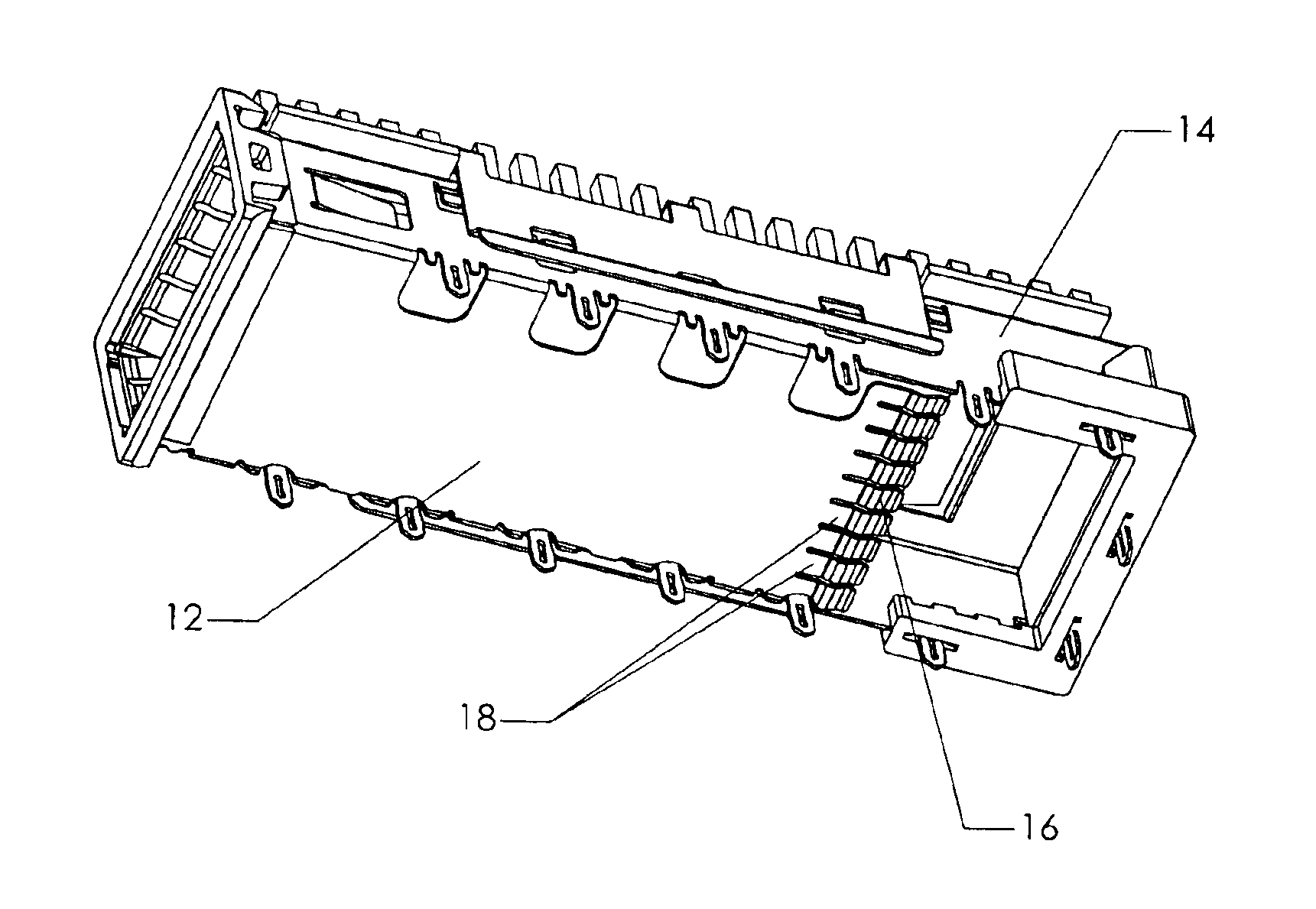
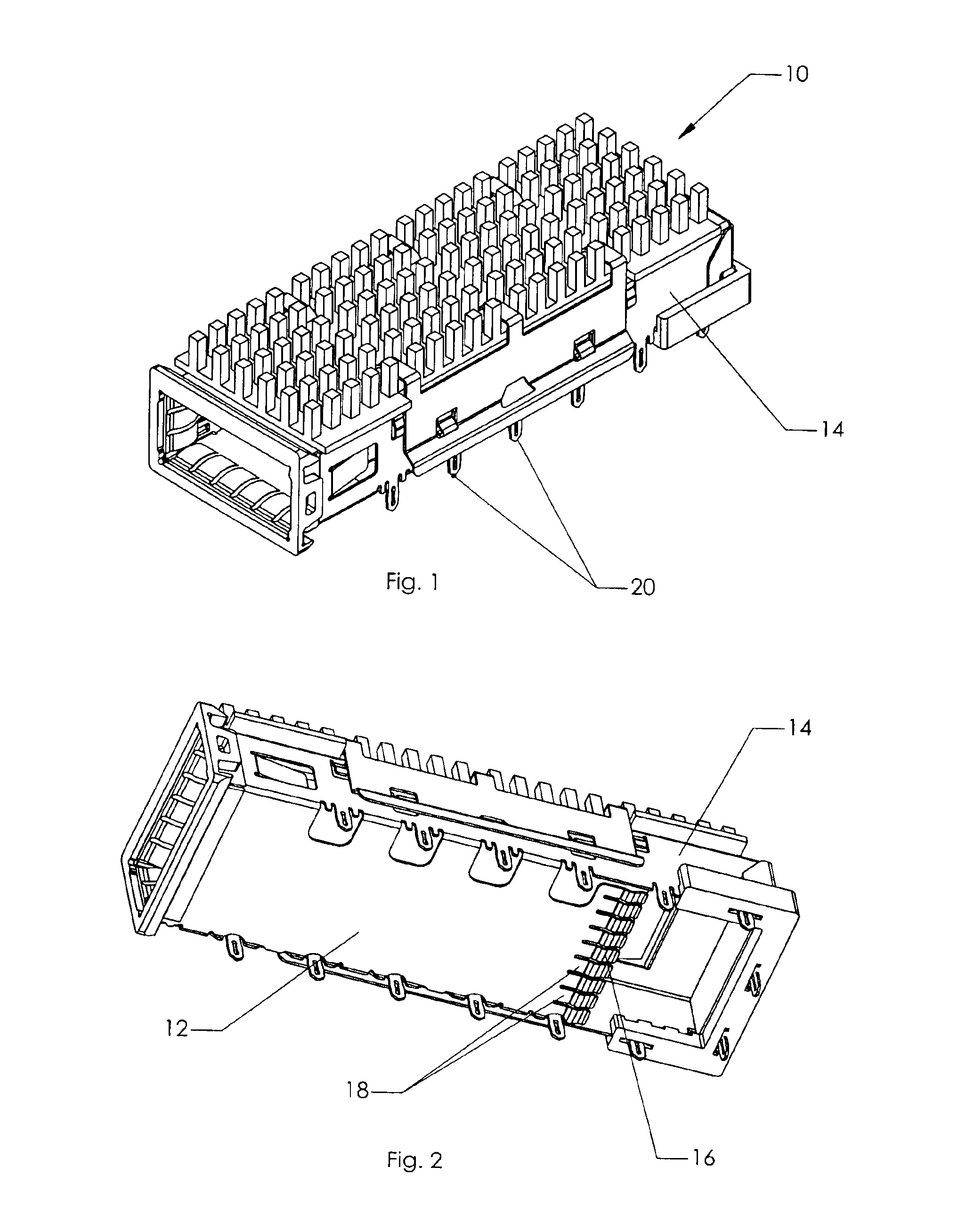
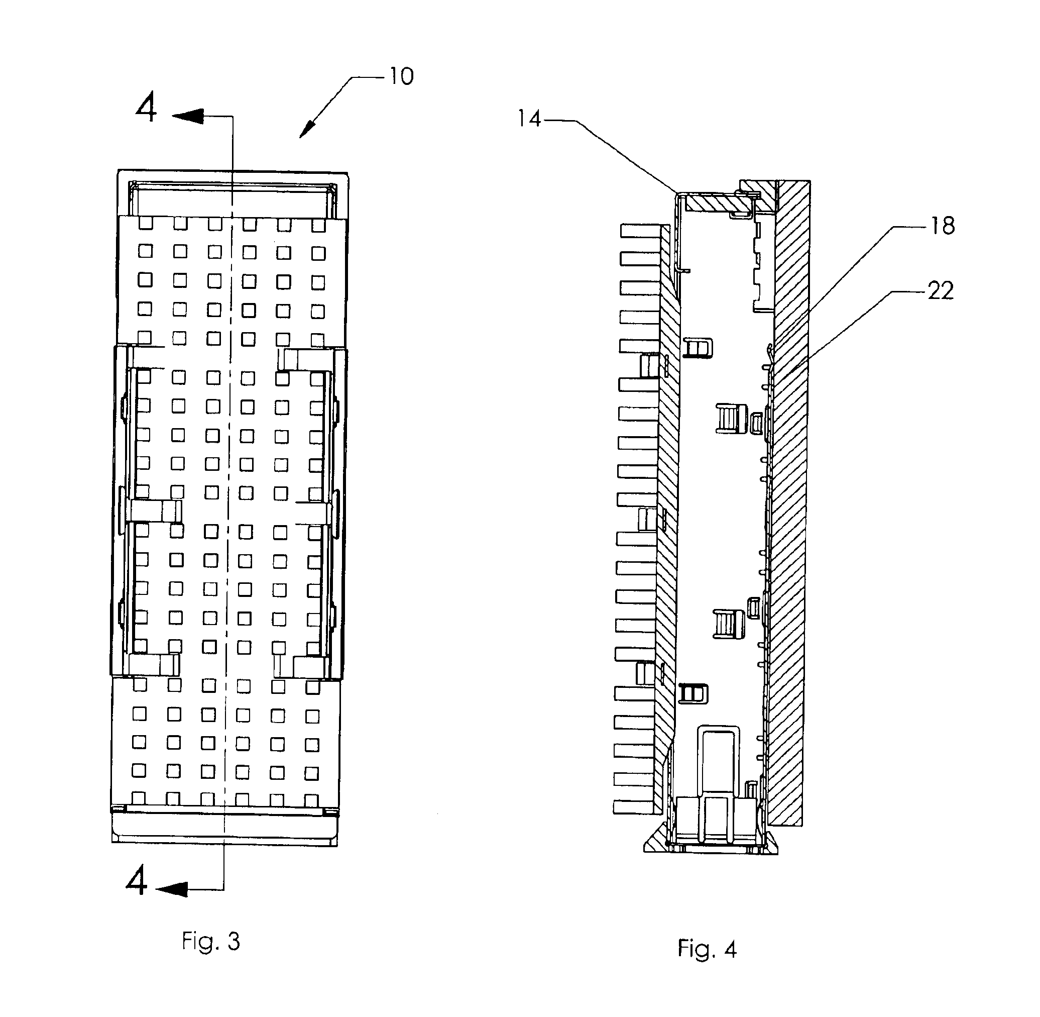
The present invention is a fiber optic transceiver package 10. The package 10 is standard many respects, but differs from the prior art significantly in the construction of the lower half 12 of the transceiver cage 14. The transceiver package 10 of the present invention integrates the intermediate rear gasket called out by the MSA specifications into the body of the transceiver package 10.

The intermediate rear gasket 16 of the present invention is comprised of a plurality of EMI fingers 18. In the preferred embodiment, the metallic fingers 18 of the intermediate rear gasket 16 are simply extensions of the lower half 12 of the metallic transceiver cage 14. As such, the EMI fingers 18 of the present invention are much thicker than current art EMI fingers. Standard EMI fingers are approximately 0.002″ thick. The integral EMI fingers 18 forming the intermediate rear gasket 16 of the present invention are 0.010″ thick.

Because of the far more rigid fingers 18, the connecting pins 20 that ...


PUM


Abstract

A package for a fiber optic transceiver that integrates the intermediate rear gasket into the lower body of the transceiver package. As such, the EMI fingers are much thicker than current art EMI fingers, 0.010″ thick as compared to current art 0.002″ thick. In current art devices, providing such robust EMI fingers is not possible. The connecting pins that secure the transceiver cage to the PCB are self-centering press-fit pins formed from a plurality of legs. At least one of the legs provides an electrical connection point for the transceiver on which the pins are used. The connecting pin is formed so that the legs act as leaf springs to securely hold the connector in place in the proper installation hole in the board on which the transceiver is installed. The pins are stamped from sheet metal with a progressive die process. By changing the amount of flexion in the legs of the pin, the pressure required to insert the pin into a connection hole, and hence the retaining pressure, can be varied.

Description

BACKGROUND OF THE INVENTION1. Field of the InventionThe present invention relates generally to fiber optic electronic components, and more particularly is a fiber optic transceiver package.2. Description of the Prior ArtComputers and related peripheral equipment, and satellite and communication systems, have in the recent past evolved extremely rapidly. These systems require ever increasing data transfer rates to perform the highly complex tasks that drive the systems, such as digital signal processing, image analysis, and communications. With current demands, optical couplers are used to transfer signals over short and long distances between computers, between two circuit boards in one computer, and even between multiple chips on a single printed circuit board. The use of high speed optical signals in place of electrical interconnections increases the achievable data transfer rate.An optical transmitter / receiver module typically includes both light emitting devices such as vertical...

Claims


Application Information

Patent Timeline
Patent Type & Authority Patents(United States)
IPC IPC(8): H05K3/30H01R12/57
CPCH01R12/585H05K3/308H05K2201/10856H05K2201/10371
Inventor BIANCHINI, GIONIFAJARDO, IGGONI
Owner FOURTE INT SDN BHD
Why Eureka
Try Eureka