Method of manufacturing a tool using a rotational processing apparatus

a technology of rotation processing and manufacturing method, which is applied in the field of tools, can solve the problems of limiting the speed and ease of manufacturing parts, affecting the life of tools, and cutting tools being worn

Inactive Publication Date: 2005-04-05
MIKRONITE TECH GROUP
View PDF36 Cites 14 Cited by
  • Summary
  • Abstract
  • Description
  • Claims
  • Application Information

AI Technical Summary

Benefits of technology

A method for forming a tool having a smooth surface finish is disclosed. The method involves the step of adding a first abrasive to a vessel. The vessel is located within a outer vessel and contains a plurality of tools. The inner vessel is rotated at high speed relative to the outer vessel. The rotation causes the first abrasive to contact the surface of the tools. After the first rotational stage is complet

Problems solved by technology

These factors limit how quickly and easily parts can be manufactured.
Cutting tool wear results from repeated contact between the cutting tool and the workpiece and directly correlates with the life of the product.
The contact between the workpiece and the cutting tool also produces friction which, in turn, generates heat that can adversely affect the life of the tool.
As such, when the abrasive surface of the saw blade contacts the abrasive surface of the cut groove, a large degree of friction results which quickly heats up the workpiece and the saw blade.
Excessive heat can result in damage to the saw blade and/or the workpiece.
Operator fatigue also red

Method used


Image

  • Method of manufacturing a tool using a rotational processing apparatus
  • Method of manufacturing a tool using a rotational processing apparatus
  • Method of manufacturing a tool using a rotational processing apparatus

Examples


Embodiment Construction

For the purpose of illustrating the invention, there is shown in the drawings one or more embodiments of the invention which are presently preferred; it being understood, however, that this invention is not limited to the precise arrangements and instrumentalities shown.

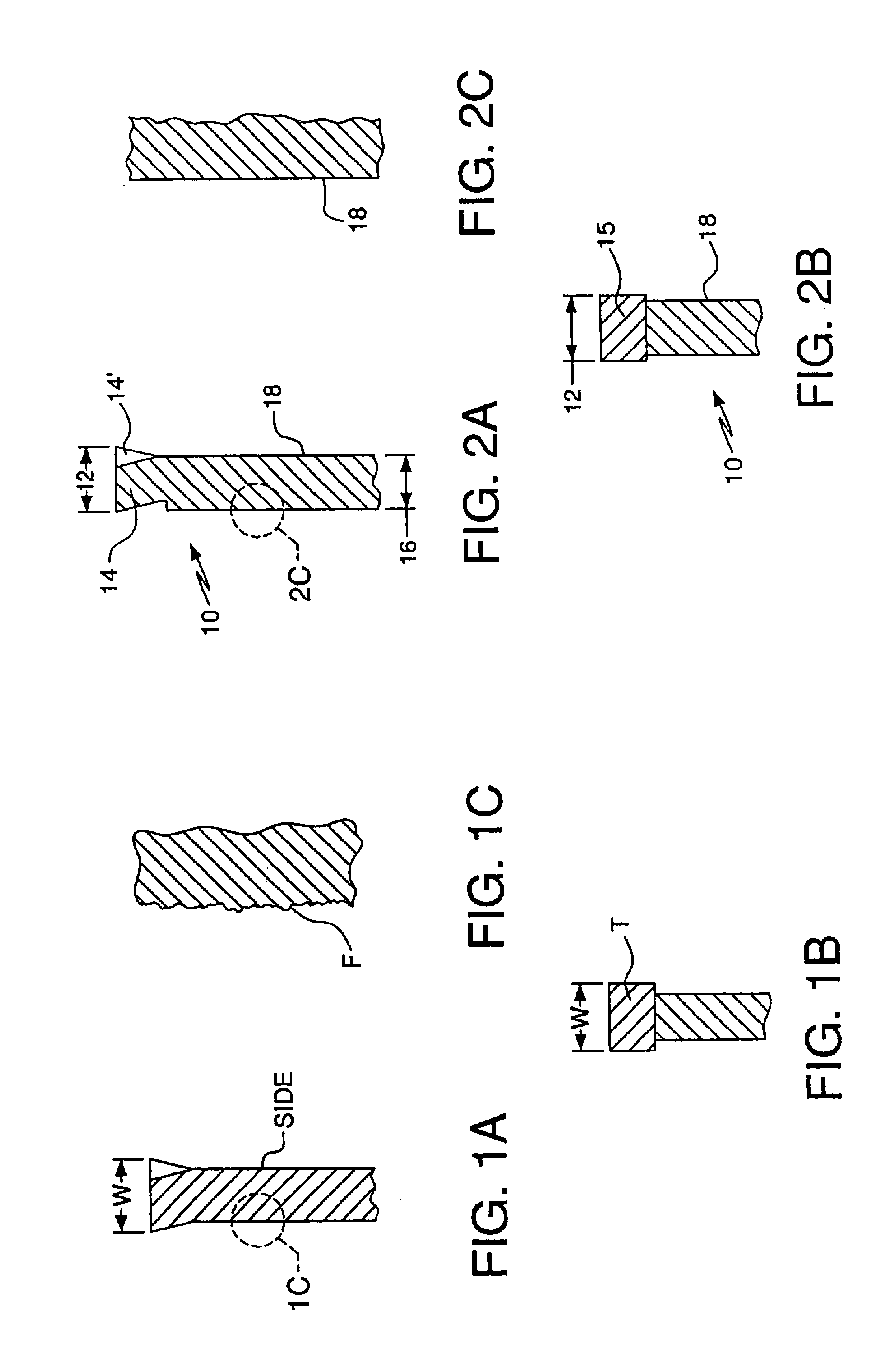
FIG. 1A illustrates a partial cross-sectional view of a conventional saw blade. As discussed above, a conventional saw blade includes a cutting tip width W which defines the spacing or clearance that will result between the cut formed in the workpiece and the blade. The cutting tip width W is defined by either the overall width of the offset teeth (called spring-setting and shown in FIG. 1A), or the actual width of the straight cutting tip T (called swage-setting and shown in FIG. 1B). A schematic representation of an enlarged detailed view of the side of the saw blade is shown in FIG. 1A, illustrating a conventional brushed steel finish F formed on the blade portion of the saw blade. A brushed steel finish is genera...


PUM

PropertyMeasurementUnit
Timeaaaaaaaaaa
Speedaaaaaaaaaa
Abrasiveaaaaaaaaaa

Abstract

A method for forming a tool having a smooth surface finish is disclosed. The method involves the step of first rotating a plurality of tools within an inner vessel at high speed relative to the outer vessel with a first abrasive. The first abrasive is then removed and a second abrasive is added to the vessel. The inner vessel is then rotated, again at high speed, with the second abrasive. The resulting tools have reduced surface anomalies.

Description

FIELD OF THE INVENTIONThe present invention relates to tools and, more particularly, to a method of manufacturing an improved saw blade using a rotational processing apparatus.BACKGROUNDThe are many factors which impact on the efficiency of a manufacturing cutting process, such as cutting tool life, operator fatigue, and inaccuracy in cutting. These factors limit how quickly and easily parts can be manufactured.Cutting tool wear results from repeated contact between the cutting tool and the workpiece and directly correlates with the life of the product. The contact between the workpiece and the cutting tool also produces friction which, in turn, generates heat that can adversely affect the life of the tool. For example, as a saw blade cuts through a workpiece, the sides of the blade contact the sides of the groove that has been cut into the workpiece. The sides of conventional saw blades have a relatively rough finish. As such, when the abrasive surface of the saw blade contacts the...

Claims


Application Information

Patent Timeline
IPC IPC(8): B23D61/00B23D61/04B23D61/02B23D65/00B24B31/02
CPCB23D61/021B23D61/025B24B31/0224B23D65/00B23D61/04B23D57/00B23D63/00Y10T83/9319
Inventor HOFFMAN, STEVE
Owner MIKRONITE TECH GROUP
Why Eureka
Try Eureka