
Coating soluble tooling inserts

a tooling insert and soluble coating technology, applied in the direction of coatings, other domestic articles, tubular articles, etc., can solve the problems of undesired “marking” on the formed part, the tooling insert cannot be easily withdrawn from the part, and the tooling insert cannot be easily withdrawn. to achieve the effect of low surface tension

Active Publication Date: 2020-01-21
THE BOEING CO
View PDF12 Cites 0 Cited by
  • Summary
  • Abstract
  • Description
  • Claims
  • Application Information

AI Technical Summary

Benefits of technology

[0007]The disclosed embodiments provide a high temperature mold release coating for a dissolvable tooling insert formed from an inorganic material having a rough or porous surface. The plastic coating fills excrescences and other surface irregularities in the ceramic tooling insert. This allows a finished molded part to be formed with a smooth surface finish. The coating has, preferentially, a low surface tension, allowing it to release from the formed plastic part, allowing easy removal from a part cavity. The coating may be a polyimide that would be suitable for use in high temperature molding operations of thermoplastics and thermosets. The coating applied to the tooling insert should be stable at the temperature of formation of the molded article.

Problems solved by technology

In those applications where the internal portions of the part are not easily accessible and / or has a complex shape, the tooling insert may not be easily withdrawn from the part after solidification and thus becomes “locked” or “trapped” within the part.
However, this approach to mold release has several disadvantages.
The use of a release film typically results in undesired “mark-off” on the formed part due to variations in the film thickness and the presence of seams between folds and overlaps of the film.
The process of applying the film is time-consuming and labor-intensive because of the care that must be taken during hand-wrapping the part.
Moreover polyimide film is relatively expensive and therefore adds to molding costs.

Method used


Image

  • Coating soluble tooling inserts
  • Coating soluble tooling inserts
  • Coating soluble tooling inserts

Examples


Embodiment Construction

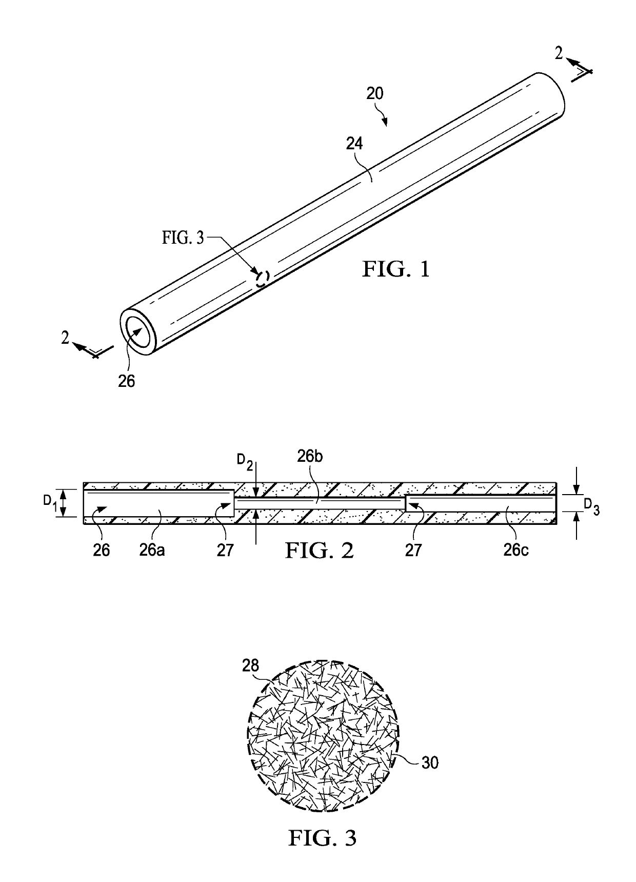
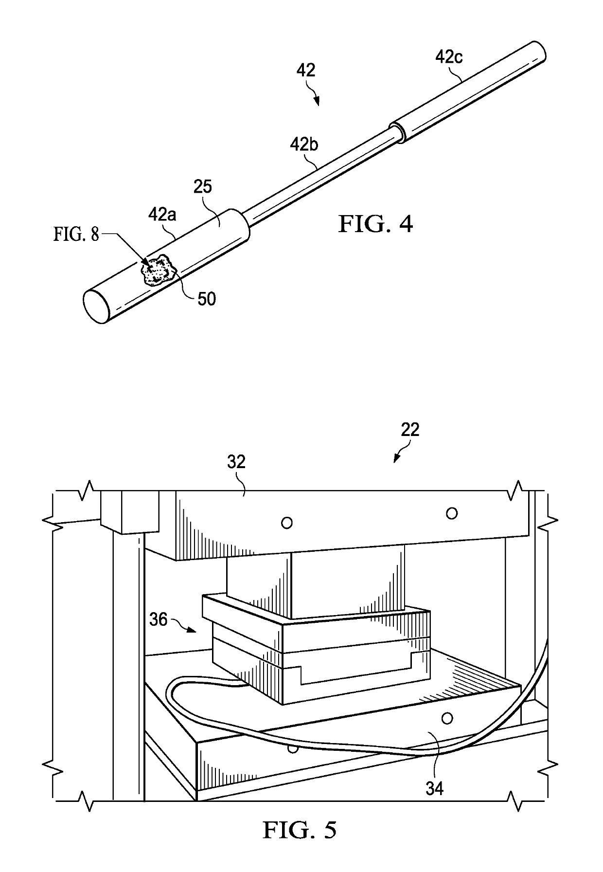
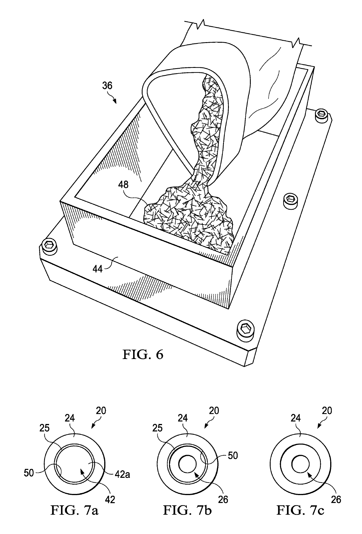
[0031]Referring first to FIGS. 1-6, a composite plastic part 20, such as a tube 20 (FIG. 1), may be molded in a heated mold tool 36 (FIG. 5) using a compression molding press 22. The mold tool 36 is compressed between upper and lower heated platens 32, 34 of the compression molding press 22. Although a simple compression molding press 22 is illustrated, the disclosed embodiments may be employed in connection with other types of molding processes, including but not limited to continuous compression molding or extrusion. Moreover, the disclosed embodiments may be employed to produce composite plastic parts, including fiber reinforced laminate parts, using any of a variety of other manufacturing processes, including but not limited to, injection molding.

[0032]The illustrated tube 20 is of a unitary, molded construction, comprising a cylindrical body 24 having an axial bore 26. The axial bore 26 may include sections 26a, 26b, 26c, respectively having different diameters D1, D2, D3 that ...


PUM

PropertyMeasurementUnit
temperatureaaaaaaaaaa
temperaturesaaaaaaaaaa
surfaceaaaaaaaaaa

Abstract

The surface of a tooling insert is coated with a polymer layer having a low surface energy in order to cover surface irregularities and thereby provide a smooth surface against which a composite part may be compression molded.

Description

BACKGROUND INFORMATION[0001]1. Field[0002]The present disclosure generally relates to processes for molding of thermoset or thermoplastic composite parts, and deals more particularly with a coating for soluble tool inserts.[0003]2. Background[0004]Hollow composite parts may be molded by placing composite material over a mandrel-like internal tooling insert that is removed after the composite structure has been molded and has achieved its final material structure. The tooling insert forms a part of a mold assembly and defines the internal shape and surface characteristics of the part. In those applications where the internal portions of the part are not easily accessible and / or has a complex shape, the tooling insert may not be easily withdrawn from the part after solidification and thus becomes “locked” or “trapped” within the part. In these applications, a dissolvable tooling insert may be employed that is formed from a soluble material that can be dissolved in solution. For exampl...

Claims


Application Information

Patent Timeline
Patent Type & Authority Patents(United States)
IPC IPC(8): B29C43/36C09D179/08B29C43/02B29L23/00
CPCC09D179/08B29C43/36B29C43/02B29K2879/08B29C2043/3668B29L2023/22
Inventor GAW, KEVIN O'BRIENLARSON, MICHAEL HARRIS
Owner THE BOEING CO
Learn More