

High friction rolling of thin metal strip
a technology of high friction and metal strips, applied in the field of thin metal strips, can solve the problems of cracking along the etched grain boundaries and the depressions resulting from the cracking, and achieve the effects of increasing the friction coefficient, eliminating the use of lubrication, and increasing the surface roughness of casting surfaces
- Summary
- Abstract
- Description
- Claims
- Application Information
AI Technical Summary
Benefits of technology
Problems solved by technology
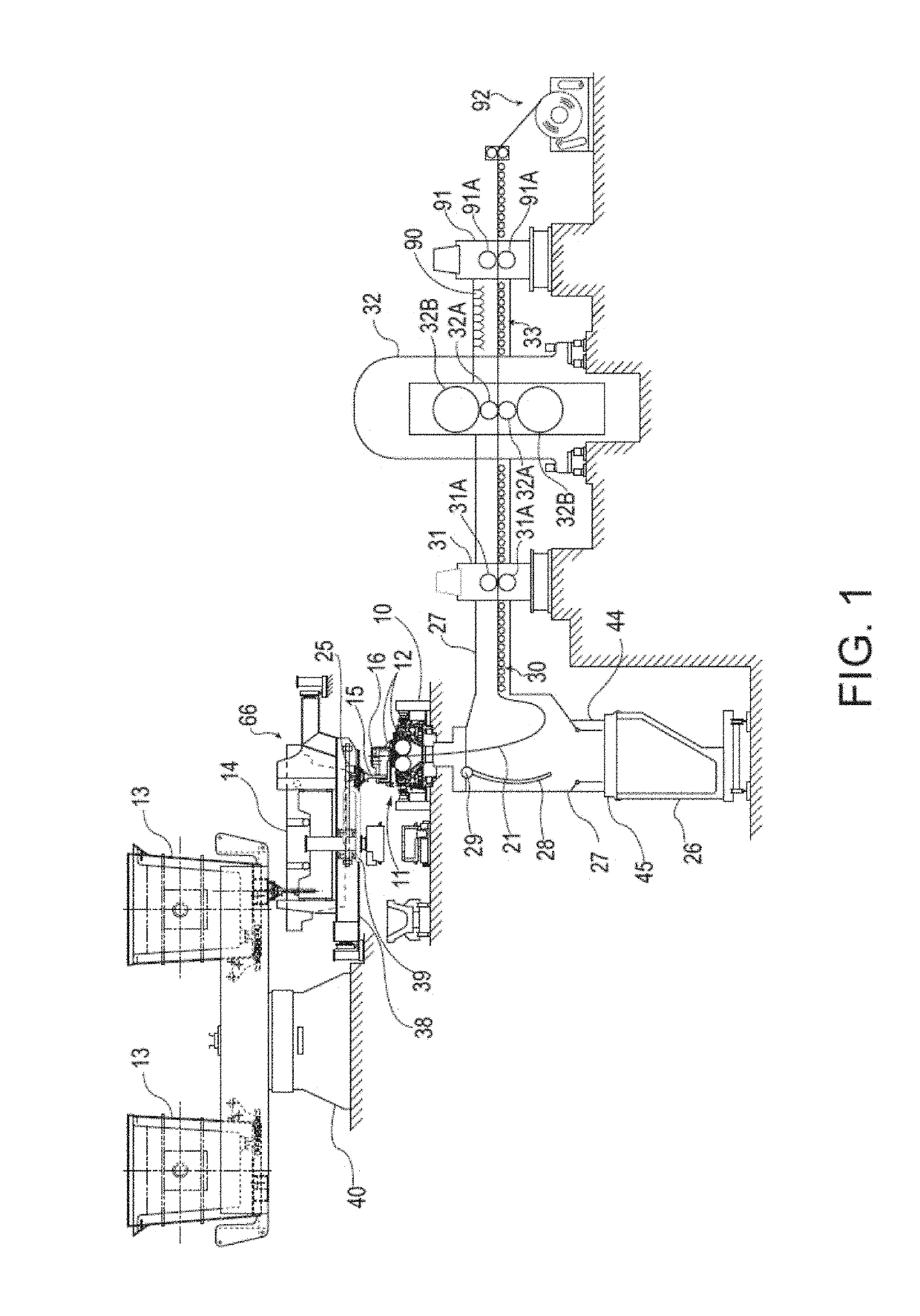
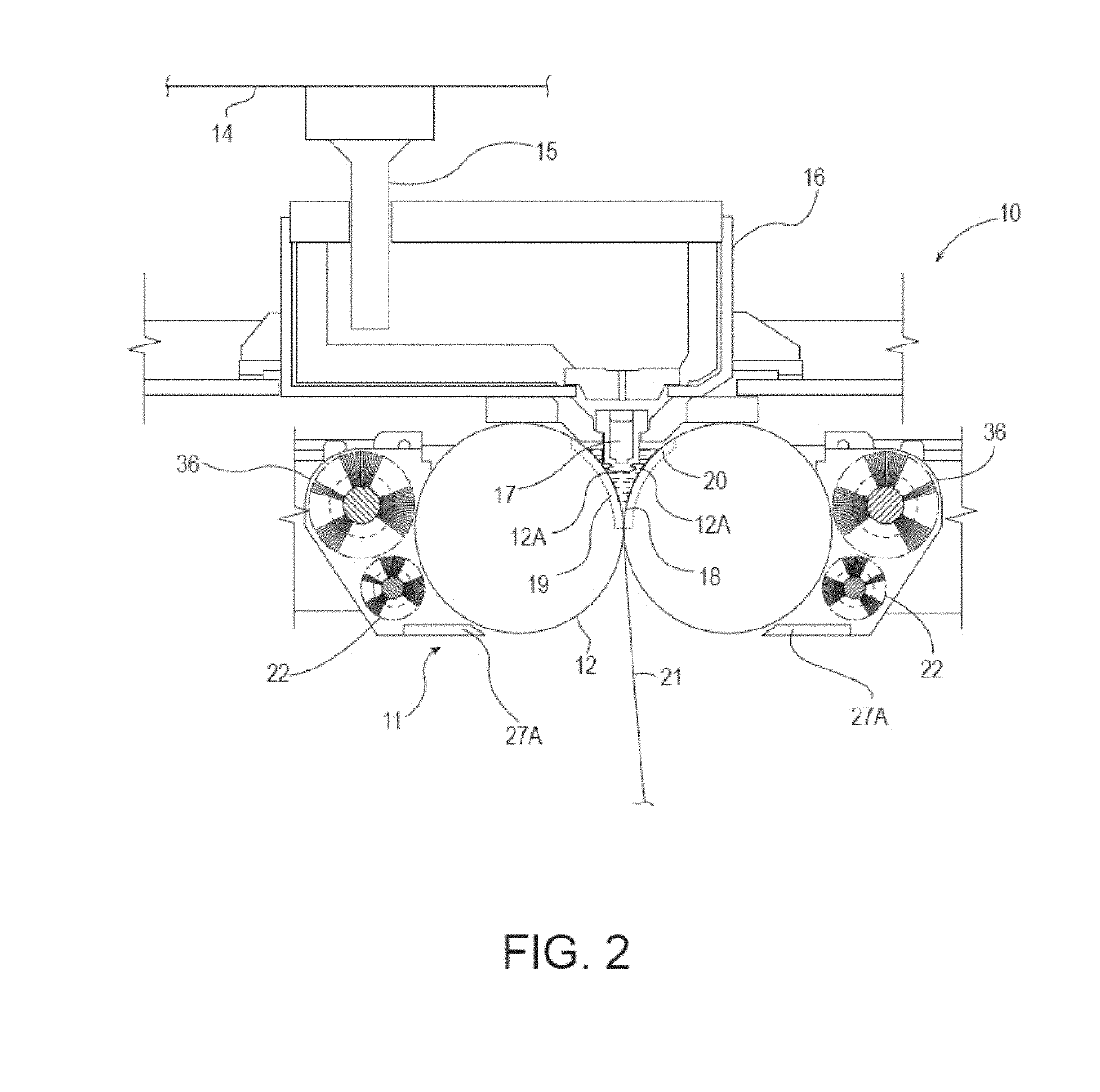
Method used
Image

Examples
Embodiment Construction
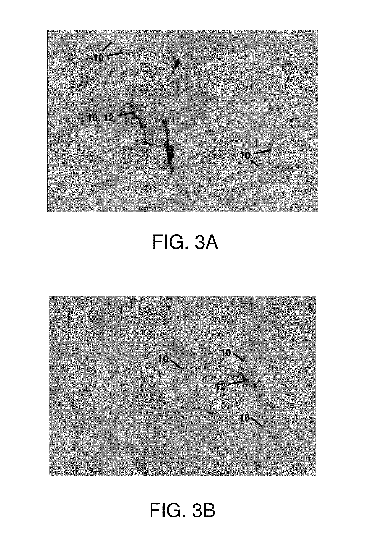
[0031]Described herein are thin metal strips characterized as having hot rolled exterior side surfaces characterized as being primarily or substantially free of all prior austenite grain boundaries, and including elongated surface structure. As a result, because the prior austenite grain boundaries are not primarily or substantially present, all such prior austenite grain boundaries are not susceptible to prior austenite grain boundary etching due to acid etching or pickling. Primarily free means less than 50% of each opposing hot rolled exterior side surface contains prior austenite grain boundaries. Substantially free means 10% or less of each opposing hot rolled exterior side surface contains prior austenite grain boundaries. Prior austenite grain boundaries form the interface between grains, where grains form crystallites in a polycrystalline material. Prior austenite grain boundaries form the interface between prior austenite grains. Determining the presence of prior austenite ...
PUM
| Property | Measurement | Unit |
|---|---|---|
| thickness | aaaaa | aaaaa |
| Ra | aaaaa | aaaaa |
| temperature | aaaaa | aaaaa |
Abstract
Description
Claims
Application Information