Method of producing electric cells using substance injection

Inactive Publication Date: 2005-04-05
TOKIN CORP
View PDF8 Cites 1 Cited by
  • Summary
  • Abstract
  • Description
  • Claims
  • Application Information

AI Technical Summary

Benefits of technology

The present invention was invented considering the circumstances described above, and the purpose of the invention is to provide a method of producing an electric cell wherein a positive electrode and an negative electrode are piled via a separator and the assembling yield of the electric cell can be improved.

Problems solved by technology

However, when the electrolytic solution is acidic, metallic materials are not used, except for some noble metals, as exterior materials, since the metallic materials are corroded.
However, in the method of forming the exterior after containing the electrolytic solution in electrodes or a separator, an electrolytic solution leaks to the surface of vulcanized rubber due to the expansion or boiling of the electrolytic solution by heating during the vulcanization binding process of the rubber, resulting in insufficient vulcanization which causes reduction in reliability of the exterior material.
Furthermore, there is a problem of limited amount of the electrolytic solution, because the amount of containing electrolytic solution in the electrodes or the separator is only that which can be impregnated previously before assembling.
And when the hole for injecting the electrolytic solution is formed after forming the exterior, there is a problem of breaking the electrodes due to the difference of hardness between the electrodes and the exterior materials and, furthermore, a problem of reduction in accuracy of processing.
When the hole for injecting the electrolytic solution is previously formed by making a hollow, cutting, or drilling a hole in the rubber, deformation and plugging of the hole may occur by the pressure and heating during the vulcanization binding process of the rubber, resulting in the reduction of the product yield.
Furthermore, there is experienced a difficulty in the process of injecting the electrolytic solution because of variable shape of the hole.

Method used


Image

  • Method of producing electric cells using substance injection
  • Method of producing electric cells using substance injection
  • Method of producing electric cells using substance injection

Examples


first embodiment

A method of producing electric cells by the present invention is explained with reference to the following drawings:

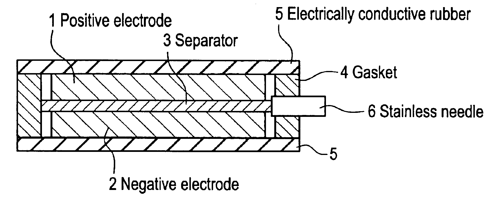
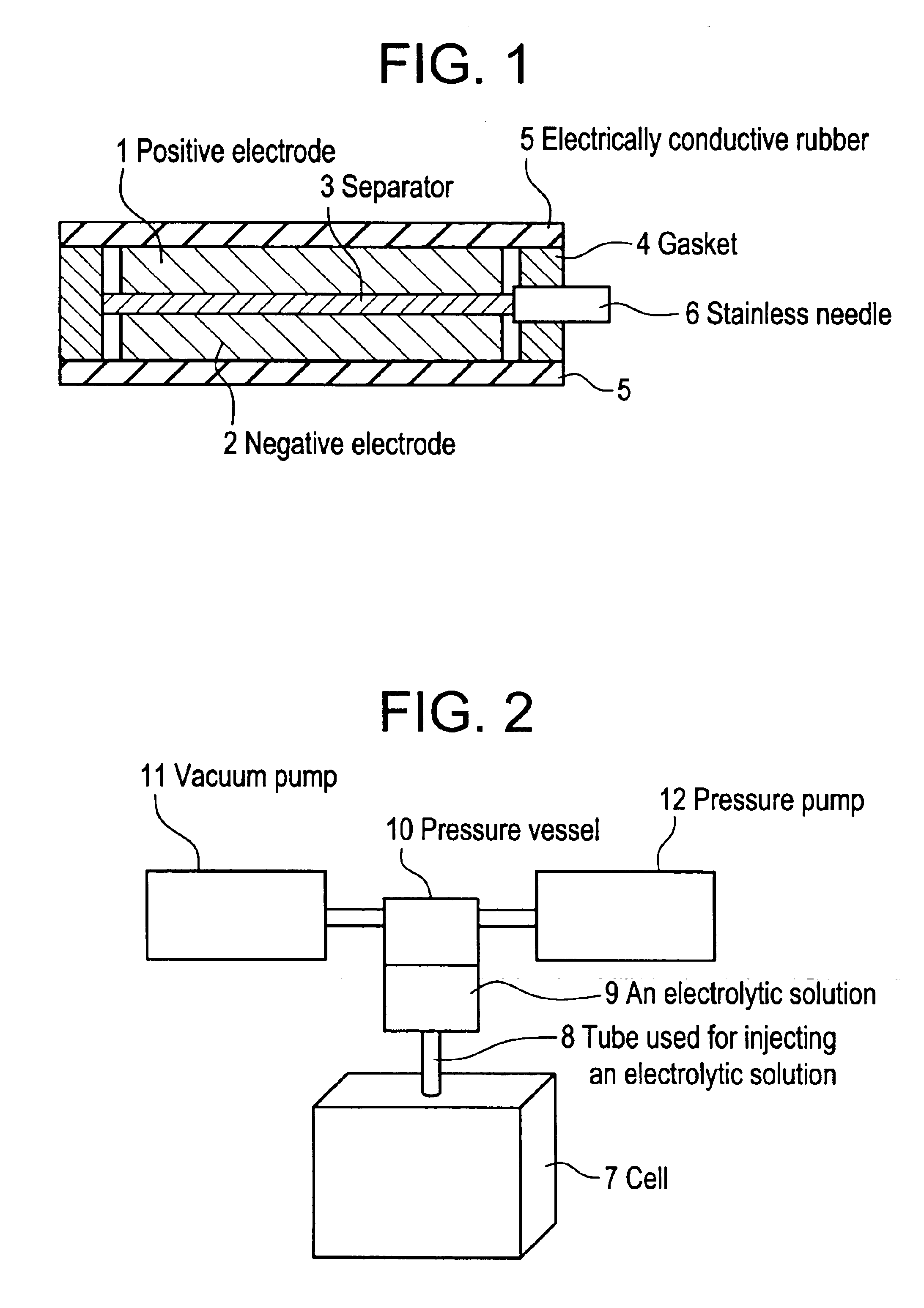
FIG. 1 is a construction drawing of the electric cell which shows the first embodiment. In this figure, 1 shows a positive electrode, 2 shows a negative electrode, 3 shows a separator separating the positive electrode 1 and the negative electrode 2. 4 shows a gasket, for which butyl rubber cut in required size (thickness:3 mm) of squared frame-like and having an insulating property is used. 5 shows electrically conductive rubber, for which butyl rubber having electrically conductive property is used. 6 shows a stainless needle used to make a hole for injecting an electrolytic solution.

FIG. 2 is a drawing showing a structure of an apparatus for injecting an electrolytic solution into the electric cell of the first embodiment. In this figure, 7 shows a minimum unit of the electric cell wherein the positive electrode 1 and the negative electrode 2 are piled via the separa...


PUM

PropertyMeasurementUnit
Electrical conductivityaaaaaaaaaa
Shapeaaaaaaaaaa

Abstract

The object of the present invention is to provide a method of producing electric cells which can improve the production yield, and for that purpose there is provided a method of producing an electric cell, wherein an acidic solution as an electrolytic solution and electrically conductive rubber as an exterior material are used, characterized in that sealing both of the positive electrode and the negative electrode piled via the separator with both of the gasket, through which the stainless needle is inserted, and the electrically conductive rubber, performing a vulcanization binding, after said vulcanization binding, forming a hole by pulling off the stainless needle from the gasket, injecting the electrolytic solution through said hole and sealing said hole; thus obtaining electric cells at high production yield.

Description

BACKGROUND OF THE INVENTION(1) Field of the InventionThe present invention relates to a method of producing an electric cell wherein a positive electrode and a negative electrode are piled via a separator and, particularly, to a method of producing an electric cell wherein an acidic solution is used as an electrolytic solution and electrically conductive rubber as exterior material.(2) Description of the Prior ArtConventionally, metallic materials, whose electrical conductivity and barrier property to liquids are excellent, are used usually as exterior materials for electric cells when an electrolytic solution used in the cell is an alkaline solution or an organic solvent. However, when the electrolytic solution is acidic, metallic materials are not used, except for some noble metals, as exterior materials, since the metallic materials are corroded. Therefore, carbonaceous materials or electrically conductive rubber materials, wherein powder of carbon (carbon filler) is dispersed, a...

Claims


Application Information

Patent Timeline
IPC IPC(8): H01G9/00H01M2/36H01M10/34H01M2/00H01M2/08H01M6/00H01M10/40H01M10/36H01M4/04H01M10/04H01M6/02H01M50/121H01M50/184H01M50/186H01M50/627
CPCH01M2/08H01M2/36H01M10/04H01M2/0257Y10T29/49115H01M2002/0297H01M2300/0005Y10T29/4911Y02E60/10H01M50/131Y02P70/50H01M50/184H01M50/186H01M50/627H01M50/121
Inventor KUROSAKI, MASATONISHIYAMA, TOSHIHIKOKAMISUKI, HIROYUKIHARADA, GAKUNAKAGAWA, YUJINOBUTA, TOMOKIMITANI, MASAYA
Owner TOKIN CORP
Why Eureka
Try Eureka