Method for coating internal surface of plasma processing chamber

a plasma processing chamber and internal surface technology, applied in plasma techniques, coatings, chemical/physical/physicochemical processes, etc., can solve the problems of no prior art example of treating internal surfaces, anodized aluminum surface cracks, and spray film may crack by heat, so as to achieve superior resistance to plasma processing and minimize mismatch in thermal expansion

Inactive Publication Date: 2005-04-05
HITACHI HIGH-TECH CORP
View PDF5 Cites 266 Cited by
  • Summary
  • Abstract
  • Description
  • Claims
  • Application Information

AI Technical Summary

Benefits of technology

In order to overcome the problems of the prior art mentioned above, the present invention provides a method for forming an internal surface of a plasma processing chamber that demonstrates superior resistance to plasma processing and thus does not cause metal contamination caused by surface wear, comprising disposing a film containing La2O3 on the surface that comes into contact with plasma, and providing an undercoat layer having a graded thermal expansion so as to minimize mismatch in thermal expansion between La2O3 and aluminum material.

Problems solved by technology

The prior art method mentioned above does not consider the influence of the heat provided to the internal surfaces of the processing chamber, and if the surfaces are subjected to thermal cycling, the sprayed film may crack by the heat.
None of the prior art examples for treating the internal surfaces of the plasma processing chamber consider the mismatch in thermal expansion of the base material, the middle layer and the surface layer.
When this chamber comes into contact with plasma, the anodized aluminum surface cracks due to the large difference in thermal expansion between aluminum and the anodization.
As a result, the aluminum material is exposed to process gas via the cracks formed to the anodized film, and corrosion occurs at the interface between the aluminum material and anodization.
As the corrosion progresses, the anodized layer exfoliates and contaminates the chamber, producing defect in the processed device.

Method used


Image

  • Method for coating internal surface of plasma processing chamber
  • Method for coating internal surface of plasma processing chamber
  • Method for coating internal surface of plasma processing chamber

Examples


first embodiment

[First Embodiment]

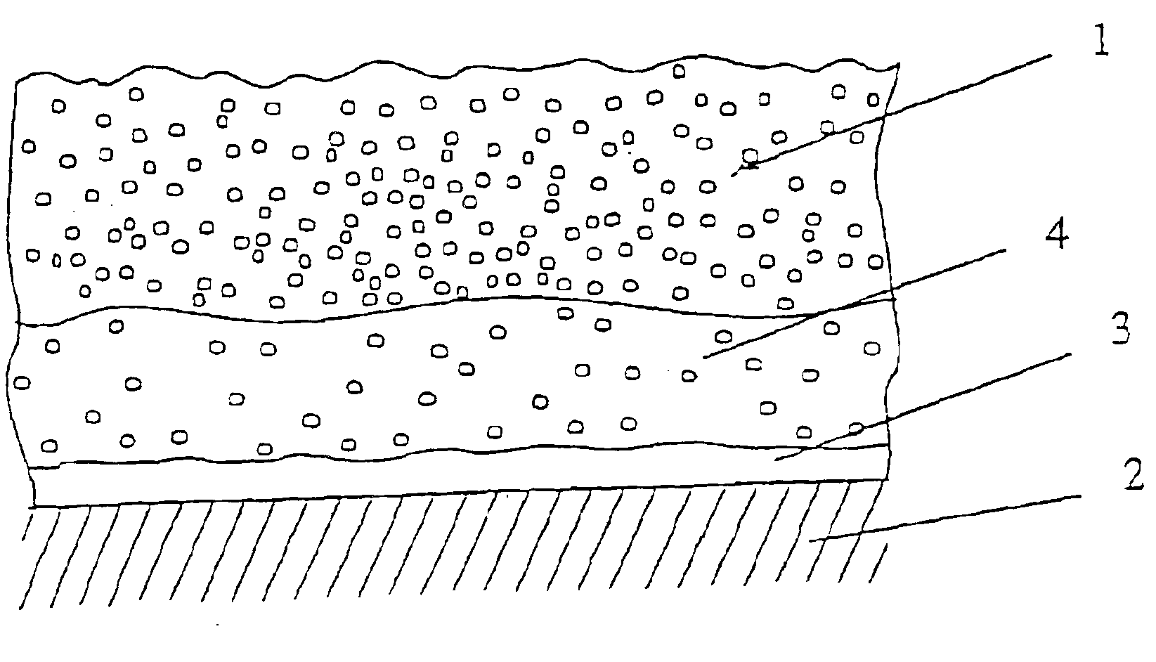
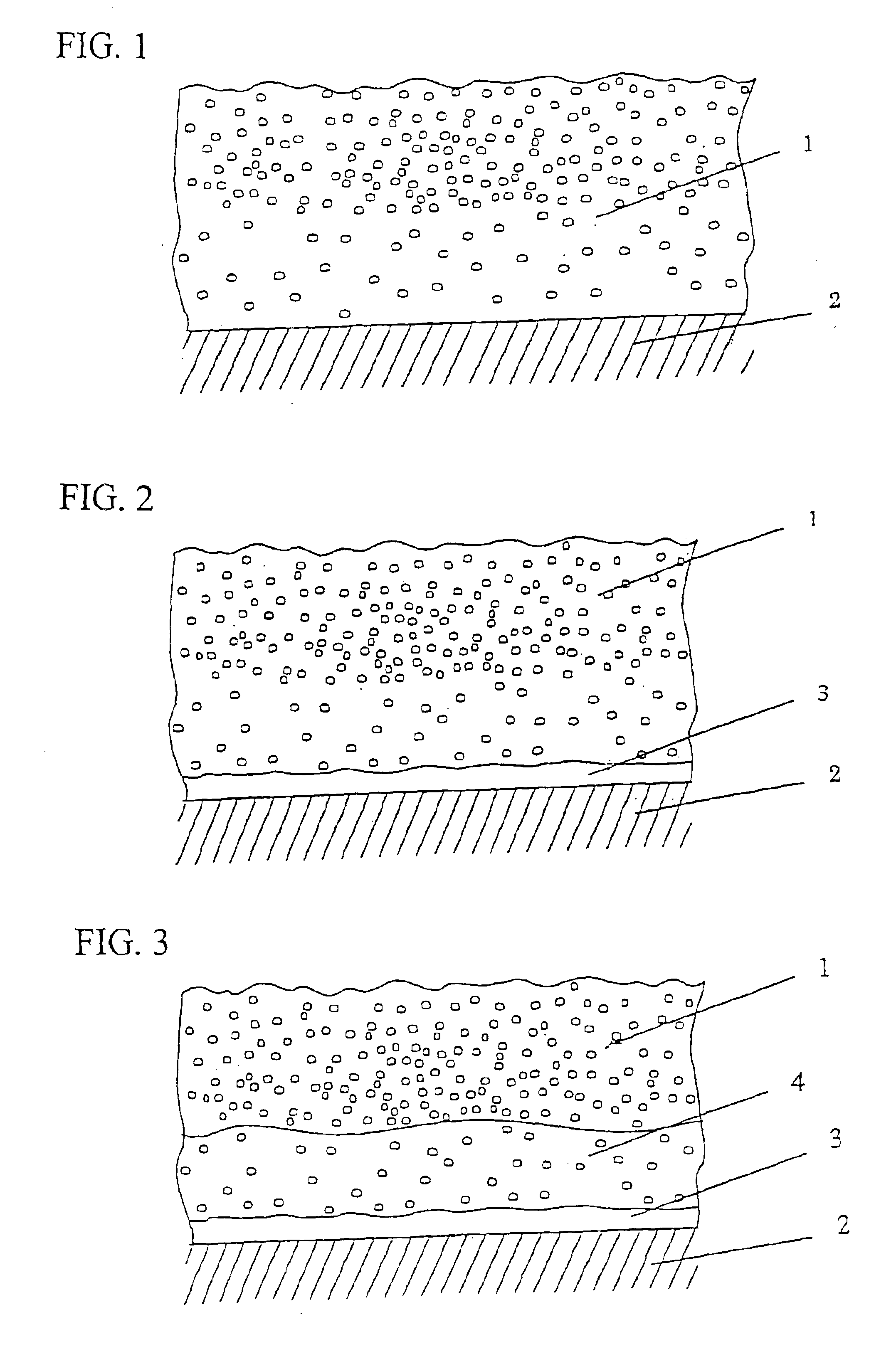
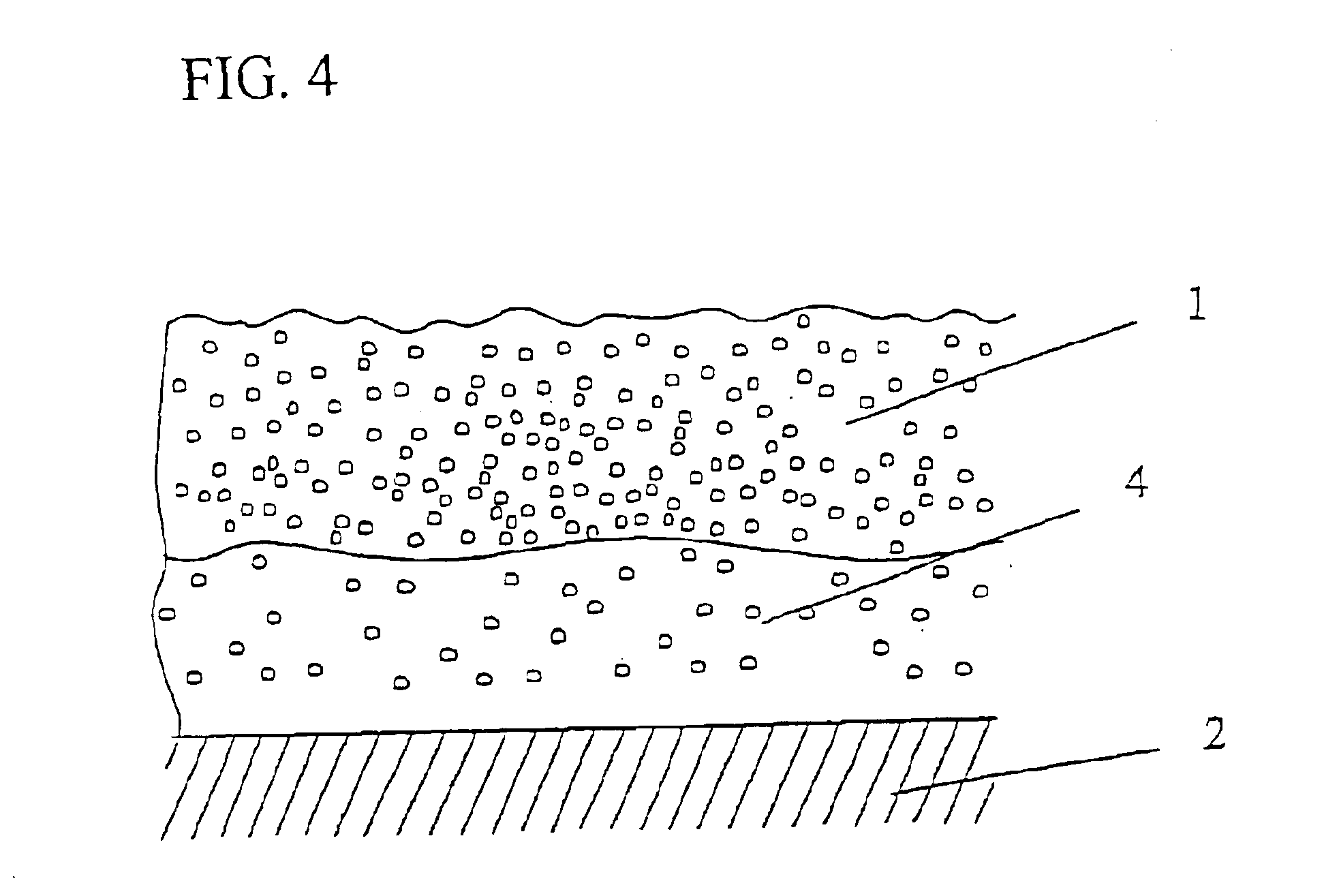
As shown in FIG. 1, the present embodiment comprises depositing on a surface of an aluminum base material 2 constituting the plasma processing chamber of the plasma processing apparatus the plasma contact surface 1 formed of a metal oxide including at least La and O via a thermal spray process. According to the present embodiment, the plasma contact surface 1 is formed of a material selected from a group consisting of La2O3, LaAlO3, MgLaAl11O19, and a mixture of La2O3 and Al2O3. The base material 2 is formed of aluminum.

example 1

La2O3 is deposited on a surface of an aluminum base material constituting the plasma processing chamber of the plasma processing apparatus via the thermal spray process to form the plasma contact surface. The La2O3 film is a single layer coating having a thickness of 5 μm to 3000 μm with a porosity between 15% and 50%.

example 2

LaAlO3 is deposited on the surface of an aluminum base material constituting a plasma processing chamber of the plasma processing apparatus via a thermal spray process to form the plasma contact surface. The LaAlO3film is a single layer coating having a thickness of 5 μm to 3000 μm with a porosity between 15% and 50%.


PUM

PropertyMeasurementUnit
temperatureaaaaaaaaaa
porosityaaaaaaaaaa
porosityaaaaaaaaaa

Abstract

The present invention comprises an aluminum base material 2 constituting the plasma processing chamber of the plasma processing apparatus, a bonding layer 3 deposited on the base material consisting of a transition metal or transition metal alloy that modifies the difference in thermal expansion coefficient of the base material and the material constituting a plasma contact surface, and the plasma contact surface 1 formed of a material selected from a group consisting of La2O3, LaAlO3, MgLaAl11O19, and a mixture of La2O3 and Al2O3 being a metal oxide including at least La and O deposited on the bonding layer 3 via a thermal spray process.

Description

FIELD OF THE INVENTIONThe present invention relates to a method for coating an internal surface of a plasma processing chamber, and especially relates to a method for treating the internal surface of the plasma processing chamber so that the exposed surface that comes in contact with plasma demonstrates a superior resistance to plasmas.DESCRIPTION OF THE RELATED ARTA prior art method for treating the surface of the plasma processing chamber comprises spraying Y2O3 on the internal surfaces of the plasma processing chamber to enhance the resistance of the exposed surface to plasmas, and disposing an undercoat containing Ni—Al and the like so as to enhance the strength of the Y2O3 film formed as a topcoat (refer for example to patent document 1).The prior art method mentioned above does not consider the influence of the heat provided to the internal surfaces of the processing chamber, and if the surfaces are subjected to thermal cycling, the sprayed film may crack by the heat. In other...

Claims


Application Information

Patent Timeline
Patent Type & Authority Patents(United States)
IPC IPC(8): C23C4/10C23C4/02H01J37/32B01J19/08H05H1/46C23F4/00H01L21/205H01L21/3065
CPCC23C4/02H01J37/32495C23C4/105C23C4/11
Inventor TRICKETT, DOUGLAS M.FURUSE, MUNEO
Owner HITACHI HIGH-TECH CORP
Why Eureka
Try Eureka