
Methods of operating a series hybrid vehicle

a hybrid vehicle and hybrid technology, applied in the direction of machines/engines, battery/cell propulsion, jet propulsion mounting, etc., can solve the problems of limited design choices, design choices affecting the size and calibration of engines in series hybrid vehicles employing previous generation energy storage devices, and achieve the effect of furthering the vehicle's overall energy efficiency gains

Inactive Publication Date: 2005-04-05
UNITED STATES OF AMERICA
View PDF59 Cites 69 Cited by
  • Summary
  • Abstract
  • Description
  • Claims
  • Application Information

AI Technical Summary

Benefits of technology

This approach enhances fuel efficiency and drivability by allowing the engine to operate at more efficient power levels, reducing energy transfer losses, and enabling the use of larger engines with faster charging energy storage devices, thereby extending trip capabilities.

Problems solved by technology

This low charge rate requirement restricts the design choices available to a hybrid vehicle designer and, in particular, restricts the choices available for a series hybrid more than it restricts the choices available for a parallel hybrid.
Thus, design choices affecting the size and calibration of an engine in a series hybrid vehicle employing previous generation energy storage devices are limited by the need to have the engine of a series hybrid produce a low enough power level to generate the required low charge rate, while still achieving greater overall energy savings from the hybrid design than would otherwise be achieved through the use of a single power source.
However, due to the low charge rate, the energy stored within previous generation energy storage devices is often used up more quickly than it can be replenished.
Thus, when the energy stored within the energy storage device of a series hybrid vehicle is depleted, the driver is unable to complete a trip because the engine alone is too small to safely propel the vehicle.

Method used


Image

  • Methods of operating a series hybrid vehicle
  • Methods of operating a series hybrid vehicle
  • Methods of operating a series hybrid vehicle

Examples


Embodiment Construction

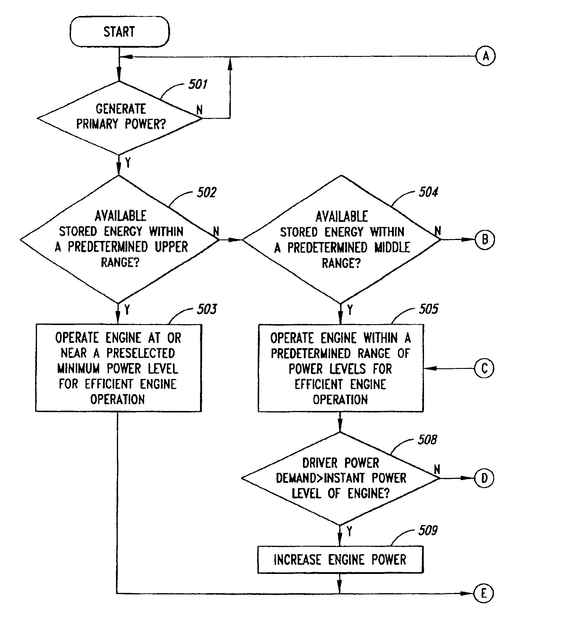
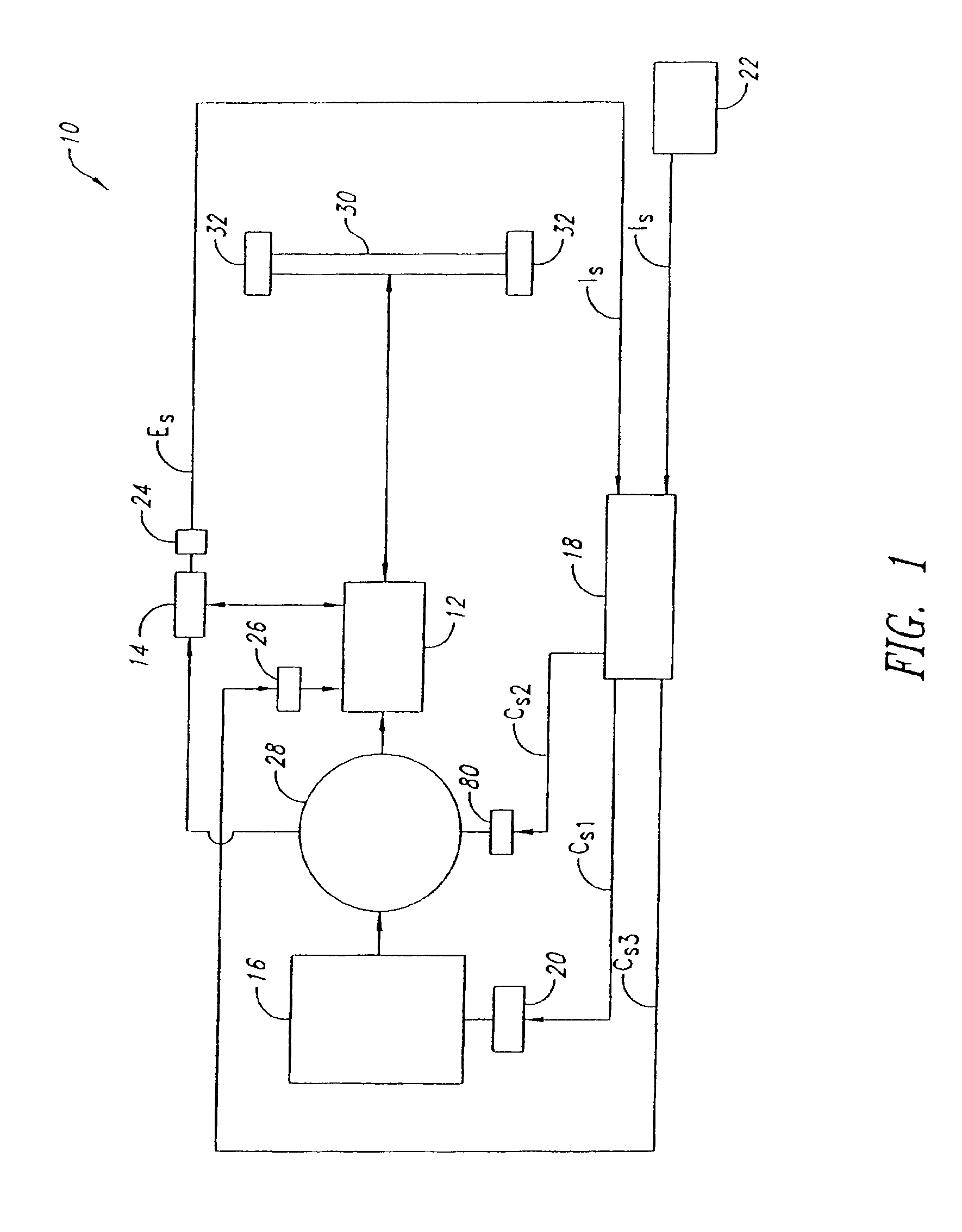
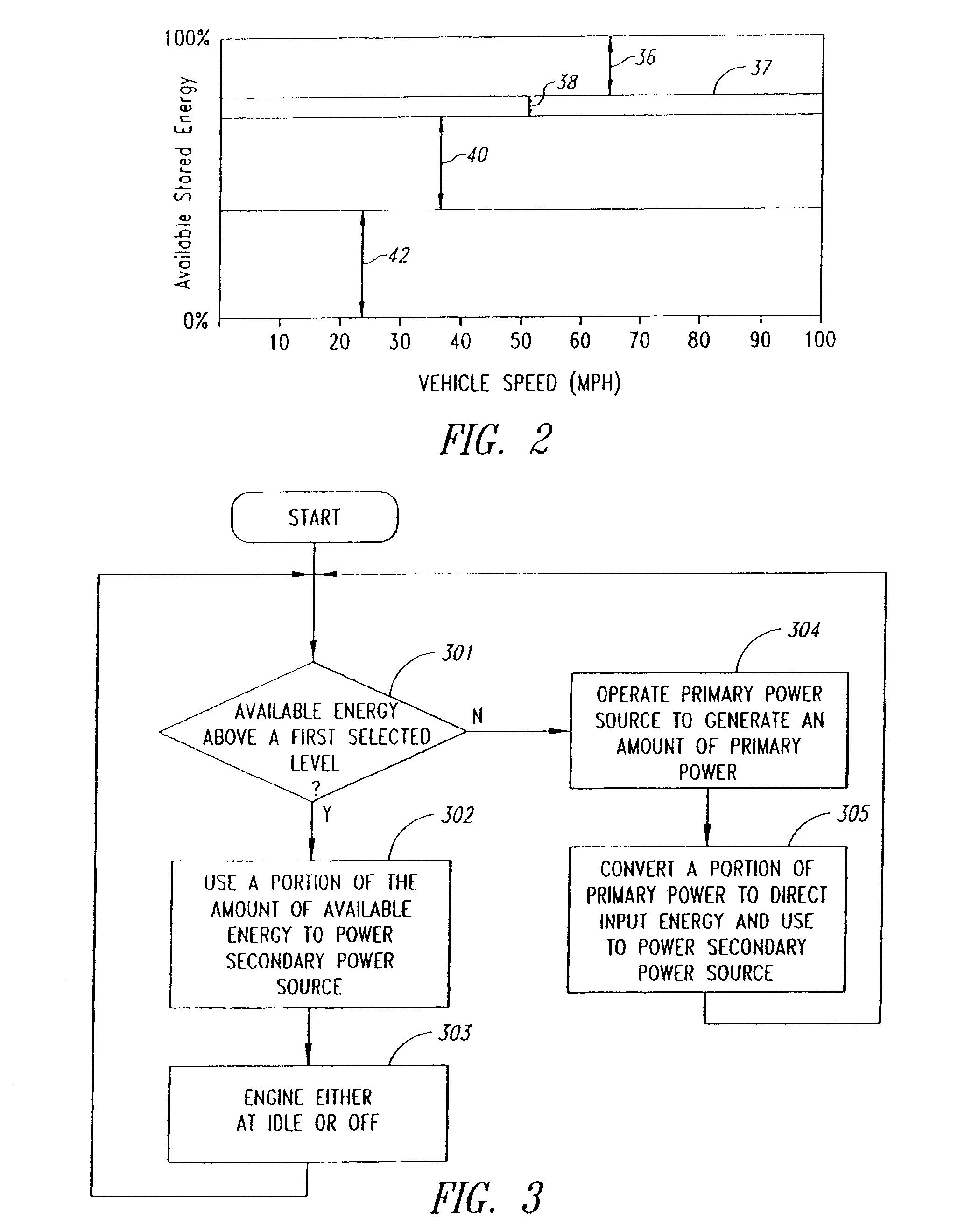
[0024]In the following description, certain specific details are set forth in order to provide a thorough understanding of various embodiments of the invention. However, one of ordinary skill in the art will understand that the invention may be practiced without these details. In other instances, well-known structures associated with hybrid vehicles have not been shown or described in detail to avoid unnecessarily obscuring descriptions of the embodiments of the invention.

[0025]The term “primary power source,” as used herein, denotes an engine such as an internal combustion engine (e.g., a compression ignition engine, a spark ignition engine, or gas turbine engine) or an external combustion engine (e.g., a Stirling engine), a fuel cell, or other primary energy converter.

[0026]The term “variable displacement engine,” as used herein, refers to a multi-cylinder engine wherein each of the cylinders is selectively operated (individually or as a group) such that the engine's total displac...


PUM


Abstract

The invention is directed toward methods for operating a series hybrid vehicle in a manner that responds to the operator's demand for power output, while maximizing engine efficiency and minimizing disruptions in vehicle drivability. According to principles of the present invention, when the driver of a series hybrid vehicle makes a demand for power output, whether the secondary power source(s) is supplied with secondary energy stored in an energy storage device(s), direct input energy generated by an engine(s), or both, depends on the amount of available secondary energy stored in the vehicle's secondary storage device(s) alone, and in combination with vehicle speed. During the time that the engine is used to generate secondary energy, the power efficiency level at which the engine is operated also depends on the vehicle speed and the amount of available secondary energy stored in the vehicle's secondary storage device alone, and in combination with vehicle speed. Further, in some embodiments, when the engine is not generating secondary energy, the engine is selectively turned off or idled in response to various operating conditions.

Description

BACKGROUND OF THE INVENTION[0002]1. Field of the Invention[0003]The present invention relates generally to methods for operating a series hybrid vehicle and, more specifically, to methods for maximizing fuel efficiency while minimizing disruptions in drivability.[0004]2. Description of the Related Art[0005]The term “hybrid vehicle,” in the broadest sense, denotes a vehicle having more than one power source and one or more energy storage means. The goal of a hybrid vehicle is to combine several similar or dissimilar types of energy stores and / or energy converters with different drive components, and operate each power source under varying operating conditions in a manner that results in greater overall energy savings than would otherwise be achieved through the use of a single power source.[0006]The primary power source of a hybrid vehicle is usually an engine powered by fuel energy (primary energy), and the secondary power source is usually, but not limited to, one or more electric ...

Claims


Application Information

Patent Timeline
Patent Type & Authority Patents(United States)
IPC IPC(8): B60K5/08B60K6/46B60L50/13B60L50/15B60W10/06B60W10/08B60W10/26B60W20/00
CPCB60K5/08B60K6/46B60W10/06B60W10/08B60W10/26B60W20/00B60L2240/12B60L50/61Y02T10/62Y02T10/70B60W10/24B60W20/13Y02T10/7072
Inventor GRAY, JR., CHARLES L.
Owner UNITED STATES OF AMERICA
Learn More