Permanent magnet synchronous motor

a permanent magnet, synchronous motor technology, applied in the direction of synchronous motors, magnetic circuit rotating parts, magnetic circuit shapes/forms/construction, etc., can solve the problems of complex manufacturing steps, inability to achieve efficient rotatory drive, and difficulty in assembling permanent magnet motors, so as to achieve accurate results, reduce the number of assembling, and facilitate the effect of job

Inactive Publication Date: 2005-04-05
PANASONIC CORP +1
View PDF22 Cites 36 Cited by
  • Summary
  • Abstract
  • Description
  • Claims
  • Application Information

AI Technical Summary

Benefits of technology

According to this structure, even if the shrinkage strain of the rotor iron core outer diameter in a radial direction increases towards the center of the rotor magnetic poles after the aluminum die casting, the outer diameter of the rotor iron core after shrinkage can be kept to the right round shape and, therefore, the gap size between the stator iron core inner diameter and the rotor iron core outer diameter can be accurately obtained merely by blanking the electromagnetic steel plates for the rotor iron core by the use of any known press work and the outer diameter of the rotor iron core need not be ground, thereby reducing the number of assembling steps. Also, since the aluminum die casting is performed while the permanent magnets and the end plates have not yet been fitted, the job can easily be performed without incurring any defective component parts, thereby increasing the productivity.
Where the permanent magnets are employed in the form of a rare earth magnet, a strong magnetic force can be obtained and both the rotor and the motor itself can advantageously manufactured in a compact size and lightweight.

Problems solved by technology

When the prior art permanent magnet motor of the type provided with the cage conductor is to be used since the conductor bars and the permanent magnets are employed as rotatory drive elements, if the conductor bars and the permanent magnets are incorrectly positioned relative to each other, a force generated from the conductor bars and a force generated by the permanent magnets will be counteracted with each other and, therefore, no efficient rotatory drive will be achieved.
Also, the permanent magnet motor provided with such a cage conductor requires a complicated and increased number of manufacturing steps since the permanent magnets and the conductor bars are provided in the rotor.

Method used


Image

  • Permanent magnet synchronous motor
  • Permanent magnet synchronous motor
  • Permanent magnet synchronous motor

Examples


second embodiment (fig.3)

Second Embodiment (FIG. 3)

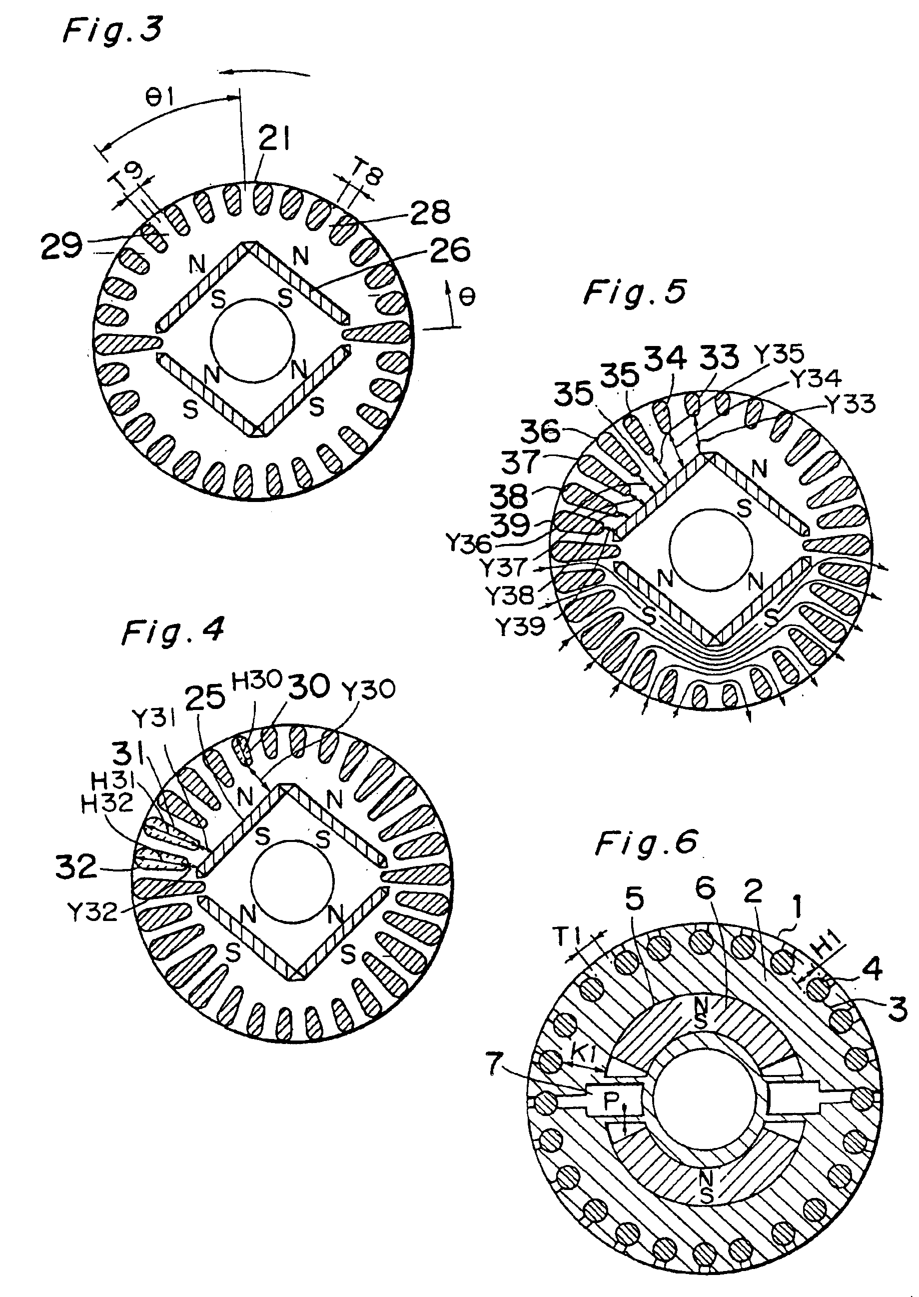
FIG. 3 illustrates a transverse sectional view of the rotor used in the self-starting permanent magnet synchronous motor according to a second preferred embodiment of the present invention. In FIG. 3, the rotor 21 is shown as rotating in a direction shown by the arrow. During a loaded operation, a composite magnetic flux of the magnetic flux emanating from the stator winding and the magnetic flux emanating from the permanent magnets 26 flows in a larger quantity in a portion 29 between the neighboring slots that are located on a leading side offset θ1 angularly in a direction conforming to the direction of rotation of the rotor, than that flowing in a portion 28 between the neighboring slots that are located on a trailing side from the center of the rotor magnetic poles with respect to the direction of rotation of the rotor. The size of that portion 29, that is, the spacing T8 between the neighboring slots on respective sides of that portion 29 is chosen to...

third embodiment (fig.4)

Third Embodiment (FIG. 4)

FIG. 4 illustrates a transverse sectional view of the rotor used in the self-starting permanent magnet synchronous motor according to a third preferred embodiment of the present invention. In FIG. 4, one of the slots that is identified by 30 is the slot positioned adjacent the center of the rotor magnetic poles, and the slots 31 and 32 are positioned adjacent one of opposite ends of the rotor magnetic poles. These slots 30, 31 and 32 have different radial lengths H30, H31 and H32, respectively, and the distances Y31 and Y32 between the slot 31 and the magnet retaining hole 25 and between the slot 32 and the magnet retaining hole 25 are chosen to be so smaller than the distance Y30 between the slot 30 and the magnet retaining hole 25 that the magnetic fluxes emanating from the permanent magnets will hardly leak to the outer peripheral surface of the rotor adjacent the ends of the rotor magnetic poles and will, instead, leak to the outer peripheral surface of ...

fourth embodiment (fig.5)

Fourth Embodiment (FIG. 5)

FIG. 5 illustrates a transverse sectional view of the rotor used in the self-starting permanent magnet synchronous motor according to a fourth preferred embodiment of the present invention. In FIG. 5, the slots 33, 34, 35, 36, 37, 38 and 39 are those positioned in a region ranging from the center to one end of the rotor magnetic poles and are spaced progressively decreasing distances Y33, Y34, Y35, Y36, Y37, Y38 and Y39, respectively, from the magnet retaining hole 35.

Arrow-headed lines shown in FIG. 5 illustrate the manner in which the magnetic fluxes of the magnetic field formed by the stator winding run across the rotor 1. For simplification purpose, the pattern of flow of the magnetic fluxed is shown only in a lower half of the rotor and not shown in an upper half of the same. As can be seen from this figure, the amount of the magnetic fluxes from the stator is small at a portion between the slot 39 adjacent the end of the rotor magnetic poles and the m...


PUM


Abstract

A synchronous motor includes a stator, a rotor and permanent magnets. The rotor includes a rotor iron core and rotatable relative to the stator, a plurality of conductor bars accommodated within corresponding slots in the rotor iron core. The conductor bars have their opposite ends shortcircuited by respective shortcircuit rings to form a starter cage conductor. The rotor also has a plurality of magnet retaining slots defined therein at a location on an inner side of the conductor bars, in which hole permanent magnets are embedded.

Description

TECHNICAL FIELDThe present invention generally relates to a permanent magnet synchronous motor and, more particularly, to the synchronous motor generally used in a motor-driven compressor in a refrigerating system or an air conditioning system or any other industrially utilized electric appliance.BACKGROUND ARTA self-starting permanent magnet synchronous motor operates as an inductor motor at the time of starting thereof owing to a starter squirrel cage conductor and as a synchronous motor as rotating magnetic poles created by the permanent magnets are entrained by a rotating magnetic field formed by a stator winding and moving angularly at a synchronous speed upon arrival of the rotor at a speed approaching the synchronous speed. This synchronous motor has an excellent constant speed operating performance and an excellent high efficiency. In particular, various improvement have hitherto been made to a rotor structure of the synchronous motor.For example, the Japanese Patent Publica...

Claims


Application Information

Patent Timeline
Patent Type & Authority Patents(United States)
IPC IPC(8): H02K1/22H02K1/27H02K17/02H02K19/14H02K21/46H02K19/02H02K21/00H02K17/26H02K3/04
CPCH02K21/46H02K1/276
Inventor SASAKI, KENJITAMURA, TERUOYOSHIDA, MICHIHIROTAKIMOTO, TORUTANIGUCHI, HIDEYUKIUESAKA, HIROYUKI
Owner PANASONIC CORP
Why Eureka
Try Eureka