Lamp inverter with pre-regulator

a technology of inverter and lamp, which is applied in the direction of instruments, basic electric elements, light sources, etc., can solve the problems of reducing so as to improve reduce the lamp current crest factor. , the effect of high ripple voltag

Inactive Publication Date: 2005-04-05
MICROSEMI CORP
View PDF30 Cites 100 Cited by
  • Summary
  • Abstract
  • Description
  • Claims
  • Application Information

AI Technical Summary

Benefits of technology

One embodiment of the present invention is a power conversion circuit with an input stage voltage regulator (or a pre-regulator) to maintain a substantially constant and relatively low lamp current crest factor for improving operation of a fluorescent lamp under various operating conditions. The pre-regulator can compensate for input voltage variations or adjust the brightness of the fluorescent lamp without significantly altering the lamp current crest factor from a desirable level. Lamp current crest factor is reduced to provide improved lamp operation.
In one embodiment, the boost regulator includes at least one semiconductor switch, a boost regulator controller, an input inductor and an output capacitor. In one embodiment, the input voltage is provided to the input inductor coupled in series with a switching transistor to ground. The output capacitor and a series-connected isolation diode or a series-connected isolation switch are coupled in parallel with the switching transistor. The boost regulator controller uses pulse width modulation techniques to provide a control signal to the switching transistor to control the storage of electrical energy in the input inductor and to control the transfer of the electrical energy to the output capacitor. The boost regulator controller operates to achieve a desired voltage across the output capacitor, which is the output of the boost regulator. For example, the boost regulator controller can vary the pulse width of the control signal to compensate for variations in the input voltage or in response to a difference between a brightness control signal and a feedback signal indicative of the lamp current level. The boost regulator controller advantageously works at relatively low voltage levels as the switching transistor is referenced to a relatively low voltage potential. The output capacitor is advantageously a relatively low cost and small component to provide a relatively high level of ripple voltage in the supply voltage, which, as discussed above, reduces the lamp crest factor.

Problems solved by technology

Fluorescent lamps are used in a number of applications where light is required but the power required to generate the light is limited.
One problem with varying the pulse widths of the driving signals is that lamp efficiency may degrade.
At the same time, the driving signals with shorter pulse widths decrease the effectiveness of signal filtering provided by the transformer's leakage inductance and output capacitance, resulting in a greater difference between the peak lamp current level and the RMS lamp current level.
Thus, the driving signals with shorter pulse widths result in higher lamp current crest factors and lower lamp lighting efficiency.

Method used


Image

  • Lamp inverter with pre-regulator
  • Lamp inverter with pre-regulator
  • Lamp inverter with pre-regulator

Examples


Embodiment Construction

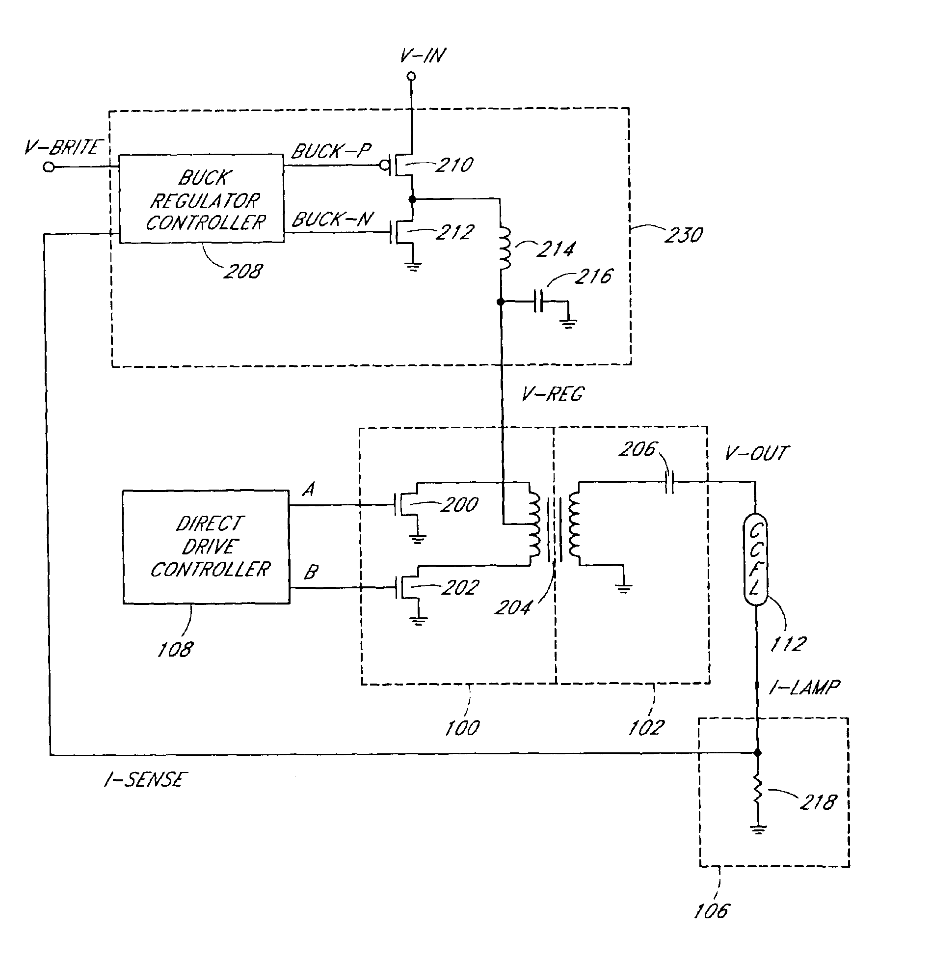
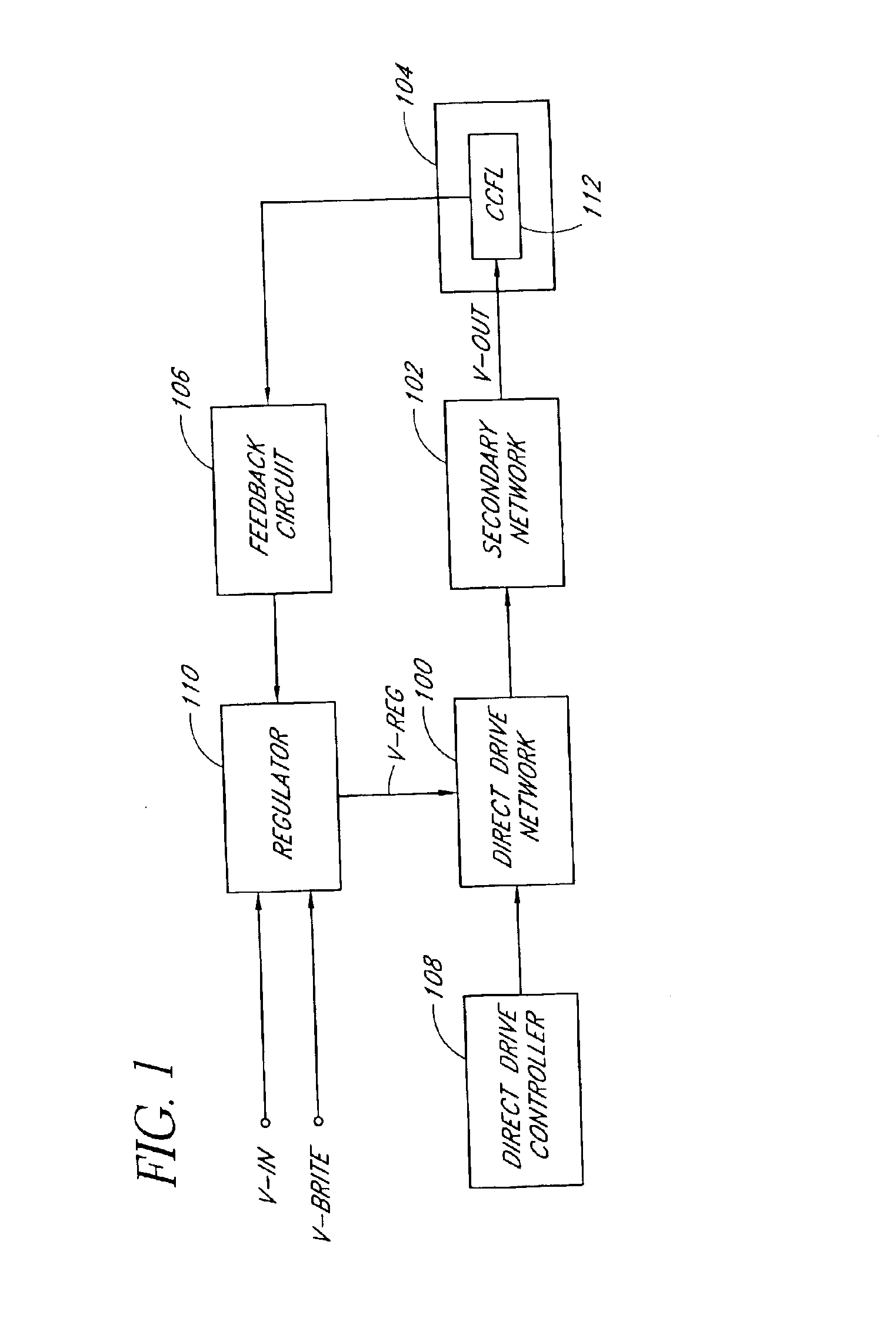
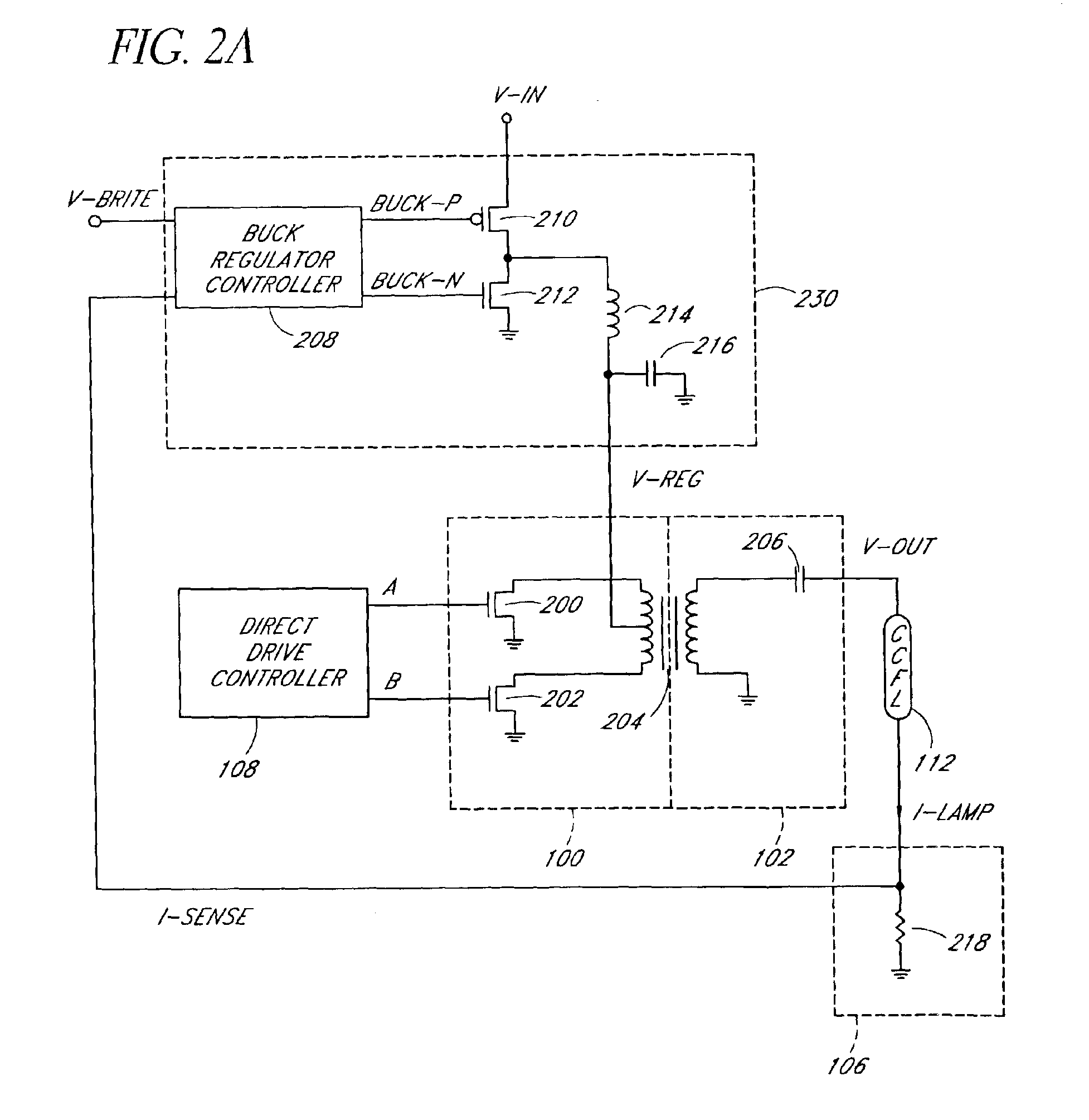
Various embodiments of the present invention will be described hereinafter with reference to the drawings. FIG. 1 is a block diagram of a power conversion circuit according to one embodiment of the present invention. The power conversion circuit converts a substantially DC input voltage (V-IN) into a substantially AC output voltage (V-OUT) to drive a CCFL 112. An AC current (or a lamp current) flows through the CCFL 112 to provide illumination in an electronic device 104, such as, for example, a flat panel display, a personal digital assistant, a palm top computer, a scanner, a facsimile machine, a copier, or the like.

The power conversion circuit includes a regulator 110, a direct drive controller 108, a direct drive network 100, a secondary network 102 and a feedback circuit 106. The regulator (or the input stage voltage regulator or the pre-regulator) 110 accepts the input voltage, a brightness control signal (V-BRITE) and a feedback signal from the feedback circuit 106 to produce...


PUM


Abstract

An efficient power conversion circuit for driving a fluorescent lamp uses a pre-regulator to generate a regulated voltage with a relatively high level of ripple voltage. The regulated voltage can be varied to provide dimming of the fluorescent lamp. The regulated voltage is provided to a direct drive inverter. The direct drive inverter uses driving signals of fixed pulse widths to generate an output voltage to drive the fluorescent lamp. The output voltage has relatively long on-time durations so that the difference between the peak lamp current and the average lamp current is reduced, thus reducing a lamp current crest factor for improved lamp lighting efficiency.

Description

RELATED APPLICATIONApplicant's copending U.S. patent application entitled “Square Wave Drive System,” filed on the same day as this application, is hereby incorporated by reference herein.BACKGROUND OF THE INVENTION1. Field of the InventionThe present invention relates to a power conversion circuit for driving fluorescent lamps, such as, for example, cold cathode fluorescent lamps (CCFLs), and more particularly relates to a lamp inverter with a pre-regulator for improved efficient operation of the CCFLs.2. Description of the Related ArtFluorescent lamps are used in a number of applications where light is required but the power required to generate the light is limited. One particular type of fluorescent lamp is a cold cathode fluorescent lamp (CCFL). CCFLs are used for back lighting or edge lighting of liquid crystal displays (LCDs), which are typically used in notebook computers, web browsers, automotive and industrial instrumentation, and entertainment systems.CCFL tubes typically...

Claims


Application Information

Patent Timeline
Patent Type & Authority Patents(United States)
IPC IPC(8): H05B41/39H05B41/282H05B41/28H05B41/392
CPCH05B41/2824H05B41/3927Y10S315/07
Inventor HENRY, GEORGE C.
Owner MICROSEMI CORP
Why Eureka
Try Eureka