Image-forming optical system

Inactive Publication Date: 2005-04-05
OLYMPUS CORP
View PDF6 Cites 21 Cited by
  • Summary
  • Abstract
  • Description
  • Claims
  • Application Information

AI Technical Summary

Benefits of technology

In view of the above-described problems associated with the prior art, an object of the present invention is to provide a high-performance and low-cost image-forming optical system using a reduced number of constituent optical elements.
It is desirable that the configuration of the first prism entrance surface in a plane containing the optical axis folded by passing through the first prism and the second prism from the stop should be a surface configuration having a convex surface directed toward the object side to give a positive power to the light beam, and the configuration of the second prism exit surface should be an approximately flat surface configuration. If the first prism entrance surface has a configuration with a convex surface directed toward the object side to give a positive power to the light beam, it is easy to effect aberration correction in the first prism, and it is possible to reduce the amount of aberrations produced in the first prism. Accordingly, the above-described arrangement is favorable. By forming the second prism exit surface into an approximately flat surface configuration, it becomes easy to unite the second prism and filters placed on the exit side thereof or a cover glass of an image pickup device, e.g. a CCD, by bonding or the like.

Problems solved by technology

Therefore, there is a limit to the reduction in thickness of the optical systems.
At the same time, the number of lens elements unavoidably increases because it is necessary to correct chromatic aberration produced by a rotationally symmetric refracting lens used in the optical systems.
Therefore, it is difficult to reduce the cost in the present state of the art.
In an example thereof, however, the number of constituent optical members is as large as five, and actual optical performance is unclear.
Accordingly, surface accuracy errors and decentration accuracy errors are transferred while being added up.
Consequently, the accuracy required for each surface becomes tight, causing the cost to increase unfavorably.
The relay of the image also causes the overall volumetric capacity of the optical system to increase unfavorably.
However, because the optical system is arranged to relay an image, the cost increases and the optical system becomes large in size unfavorably for the same reasons as stated above.
However, the optical system is not satisfactorily corrected for aberrations.
In a decentered prism optical system, it is difficult to predict ghost light (stray light).
Similarly, when a prism is placed closer to the object side than an aperture stop, because the height of extra-axial rays is high, the effective surface area of the prism is inevitably large.
To correct the chromatic aberration and also correct other ray aberrations, the refracting optical system needs a large number of constituent elements, causing the cost to increase.
In addition, because the optical path extends straight along the optical axis, the entire optical system undesirably lengthens in the direction of the optical axis, resulting in an unfavorably large-sized image pickup apparatus.
In decentered optical systems such as those described above in regard to the prior art, an imaged figure or the like is undesirably distorted and the correct shape cannot be reproduced unless the formed image is favorably corrected for aberrations, particularly rotationally asymmetric distortion.
Furthermore, in a case where a reflecting surface is used in a decentered optical system, the sensitivity to decentration errors of the reflecting surface is twice as high as that in the case of a refracting surface, and as the number of reflections increases, decentration errors increase correspondingly because they are transferred while being added up.
Consequently, manufacturing accuracy and assembly accuracy, e.g. surface accuracy and decentration accuracy, required for reflecting surfaces become even more strict.
Thus, it is becoming difficult to ensure the required performance with only one prism.

Method used


Image

  • Image-forming optical system
  • Image-forming optical system
  • Image-forming optical system

Examples


examples 1 and 2

of the image-forming optical system according to the present invention will be described below.

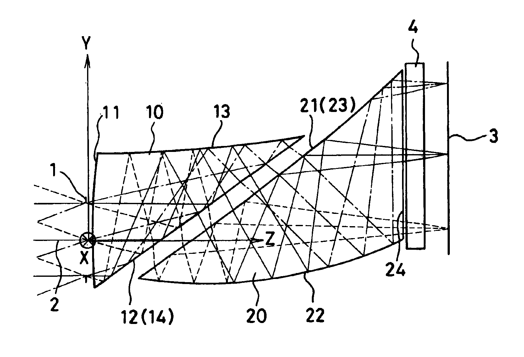
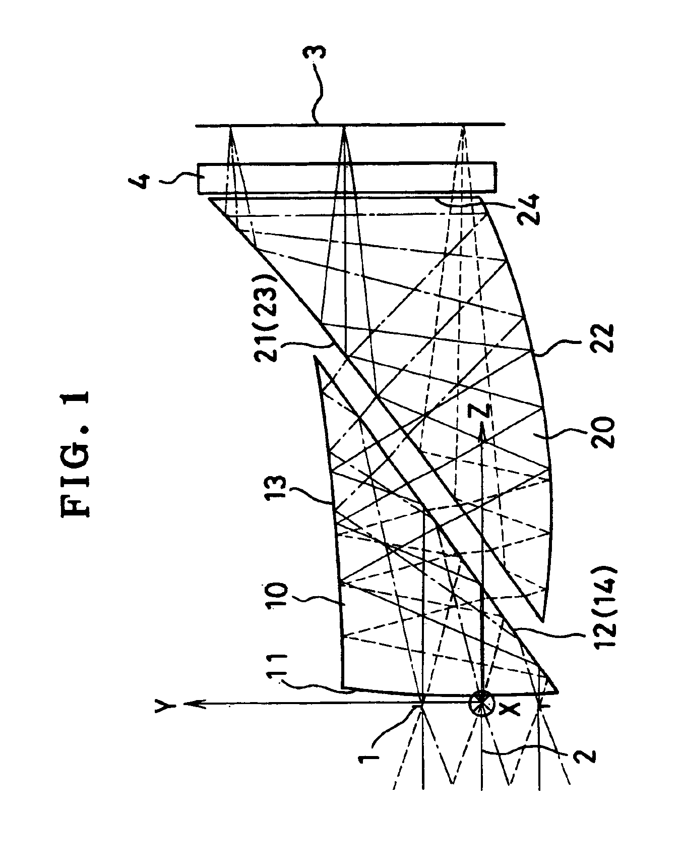
Constituent parameters of Examples 1 and 2 will be shown later. In the constituent parameters, surface Nos. are shown as surface Nos. in forward ray tracing from an object through a stop 1 to an image plane 3. Regarding the definition of coordinates, as shown in FIG. 1, an axial principal ray 2 is defined by a light ray passing through the center of the stop 1 and reaching the center of the image plane 3 (the image pickup surface of an image pickup device). An intersection between the axial principal ray 2 and the plane of the stop 1 is defined as the origin of a decentered optical surface. The direction along the axial principal ray 2 is defined as a positive direction of a Z-axis. A plane containing both the Z-axis and the center of the image plane 3 is defined as a YZ-plane. An axis passing through the origin and perpendicularly intersecting the YZ-plane is defined as an X-axis. The dir...

example 1

SurfaceRadius ofSurfaceDisplacementRefractiveAbbe'sNo.curvatureseparationand tiltindexNo.Object∞∞plane1∞ (Stop)2FFS①(1)1.525455.83FFS②(2)1.525455.84FFS③(3)1.525455.85FFS②(2)6FFS④(4)1.525455.87FFS⑤(5)1.525455.88FFS④(4)1.525455.89∞(6)10∞(7)1.516364.111∞(8)Image∞(9)planeFFS①C4 5.4038 × 10⁻²C6 1.8678 × 10⁻²FFS②C4 1.2719 × 10⁻³C6−2.0180 × 10⁻³C8 6.9200 × 10⁻⁴C10−3.2115 × 10⁻⁴C11−1.7770 × 10⁻⁴C13 9.7017 × 10⁻⁵C15−1.5867 × 10⁻⁵FFS③C4−1.7204 × 10⁻²C6−1.1421 × 10⁻²C8 2.6819 × 10⁻³C10−6.9701 × 10⁻⁴C11−3.2922 × 10⁻⁴C13 1.9243 × 10⁻⁴C15−3.7214 × 10⁻⁵FFS④C4−2.3174 × 10⁻²C6−4.5848 × 10⁻³C8−2.2925 × 10⁻⁴C10−5.4406 × 10⁻⁴C11 1.7325 × 10⁻⁴C13−4.0761 × 10⁻⁶C15−3.7446 × 10⁻⁵FFS⑤C4−4.5549 × 10⁻²C6−3.5862 × 10⁻²C8 1.0022 × 10⁻³C10−3.1292 × 10⁻⁴C11−1.0085 × 10⁻⁴C13−1.7098 × 10⁻⁴C15−5.5848 × 10⁻⁶Displacement and tilt(1)X0.00Y0.00Z0.20α0.00β0.00γ0.00Displacement and tilt(2)X0.00Y−0.00Z2.37α−56.36β0.00γ0.00Displacement and tilt(3)X0.00Y...

example 2

SurfaceRadius ofSurfaceDisplacementRefractiveAbbe'sNo.curvatureseparationand tiltindexNo.Object∞∞plane1ASS①2.001.525455.825.322.323∞ (Stop)4FFS①(1)1.525455.85FFS②(2)1.525455.86FFS③(3)1.525455.87FFS②(2)8FFS④(4)1.525455.89FFS⑤(5)1.525455.810FFS④(4)1.525455.811∞(6)12∞(7)1.516364.113∞(8)Image∞(9)planeASS①R−0.19K−5.3042 × 10¹²A 3.2263 × 10⁻⁴B 9.4407 × 10⁻⁶FFS①C4 9.4601 × 10⁻²C6 9.4063 × 10⁻²FFS②C4 7.0060 × 10⁻³C6 3.4313 × 10⁻³C8 4.4086 × 10⁻⁴C10 4.1181 × 10⁻⁴C11 3.8467 × 10⁻⁴C13−8.7750 × 10⁻⁶C15 2.3939 × 10⁻⁵FFS③C4−1.0899 × 10⁻²C6−1.1224 × 10⁻²C8 2.4936 × 10⁻³C10 2.7277 × 10⁻³C11 1.4602 × 10⁻⁵C13−3.1706 × 10⁻⁴C15 6.5358 × 10⁻⁵FFS④C4−3.6243 × 10⁻²C6−1.6563 × 10⁻²C8−2.2006 × 10⁻³C10−1.5026 × 10⁻³C11 2.4606 × 10⁻⁴C13−9.1150 × 10⁻⁵C15−6.4463 × 10⁻⁵FFS⑤C4−5.0002 × 10⁻²C6−4.1129 × 10⁻²C8 3.4936 × 10⁻⁴C10 1.8044 × 10⁻⁴C11−1.1817 × 10⁻⁴C13−2.3358 × 10⁻⁴C15−4.8676 × 10⁻⁵Displacement and tilt(1)X0.00Y0.00Z0.20α0.00...


PUM


Abstract

A high-performance and low-cost image-forming optical system with a reduced number of constituent optical elements that is made compact and thin by folding an optical path using reflecting surfaces arranged to minimize the number of reflections. The image-forming optical system has a first prism and a second prism between a stop and an image plane. The first prism includes an entrance surface, a first reflecting surface, a second reflecting surface, and an exit surface. The first reflecting surface and the exit surface are the identical surface. The second prism includes an entrance surface, a first reflecting surface, a second reflecting surface, and an exit surface. In the second prism, the second reflecting surface and the entrance surface are the identical surface.

Description

BACKGROUND OF THE INVENTIONThe present invention relates to image-forming optical systems. More particularly, the present invention relates to a decentered optical system with a reflecting surface having a power for use in optical apparatus using a small-sized image pickup device, e.g. video cameras, digital still cameras, film scanners, and endoscopes.Recently, with the achievement of small-sized image pickup devices, image-forming optical systems for use in video cameras, digital still cameras, film scanners, endoscopes, etc. have also been demanded to be reduced in size and weight and also in cost.In the general rotationally symmetric coaxial optical systems, however, optical elements are arranged in the direction of the optical axis. Therefore, there is a limit to the reduction in thickness of the optical systems. At the same time, the number of lens elements unavoidably increases because it is necessary to correct chromatic aberration produced by a rotationally symmetric refrac...

Claims


Application Information

Patent Timeline
IPC IPC(8): G02B17/08H04N5/225
CPCG02B17/0848H04N5/2254G02B17/086H04N2005/2255H04N23/555H04N23/55H04N23/63
Inventor NAGATA, TETSUO
Owner OLYMPUS CORP
Why Eureka
Try Eureka