
Filter circuit for a bit pump and method of configuring the same

Inactive Publication Date: 2005-04-05
LUCENT TECH INC
View PDF22 Cites 15 Cited by
  • Summary
  • Abstract
  • Description
  • Claims
  • Application Information

AI Technical Summary

Benefits of technology

To address the above-discussed deficiencies of the prior art, the present invention provides a filter circuit, method of configuring the filter circuit, and a bit pump and transceiver employing the circuit and method. In one embodiment, the filter circuit includes a noise prediction equalizer that generates a noise prediction equalizer coefficient during activation of the bit pump to reduce an intersymbol interference associated with a receive signal propagating along a receive path of the bit pump. The filter circuit also includes a decision feedback equalizer that generates a decision feedback equalizer coefficient during the activation of the bit pump to reduce the intersymbol interference associated with the receive signal. The noise prediction equalizer is concatenated with the decision feedback equalizer during showtime of the bit pump to form a precoder associated with a transmit path of the bit pump.
The present invention introduces, in one aspect, a filter circuit that performs an equalization function during the activation of the bit pump and is reconfigured as a precoder during showtime of the bit pump. During activation, the various adaptive circuits of the bit pump are trained to optimize their performance associated with a particular operating environment. Showtime begins when activation is complete and a condition of data transparency exists allowing stable operation of the bit pump. At the inception of showtime, the noise prediction equalizer and the decision feedback equalizer along with their coefficient values developed during activation are reconfigured to serve as the precoder. The reconfiguration provides a more effective solution for performance enhancement of the bit pump during showtime.
In one embodiment of the present invention, the noise prediction equalizer and the decision feedback equalizer include noise prediction equalizer and decision feedback equalizer coefficient arrays respectively associated therewith. The coefficient arrays, associated with the noise prediction equalizer and the decision feedback equalizer, contain filter coefficients that determine the response of these units. In an embodiment to be illustrated and described, the coefficients are adaptively determined to enhance the system performance.

Problems solved by technology

Unfortunately, signal quality suffered greatly as distances increased.
Filters and amplifiers improved quality, but only to a limited extent.
Thus, it was decided that higher frequencies were of limited value and represented a waste of bandwidth if the traffic were to be digitized and transmitted.
Unfortunately, even in view of the most clever modems, the 4 kHz digitization cutoff has imposed an apparent limit on the speed of such devices.
Unfortunately, the analog local loops have unjustly taken most of the blame for the speed limitation.
Third, DSL-based technology requires relatively little equipment to combine and later separate speech and data streams.
Some technical challenges, however, remain for HDSL2.
Error propagation may occur as a result of incorrect decisions often made in a feedback section of other filter circuits not employing preceding techniques.
Without the modulo operator, the feedback filter would behave like a recursive filter, which could become unstable depending on the values of its filter coefficients.
Unfortunately, the cost of hardware needed to accomplish this function is also proportional to the number of stages used and therefore may be prohibitive or an impediment for many applications requiring an appropriate performance.

Method used


Image

  • Filter circuit for a bit pump and method of configuring the same
  • Filter circuit for a bit pump and method of configuring the same
  • Filter circuit for a bit pump and method of configuring the same

Examples


Embodiment Construction

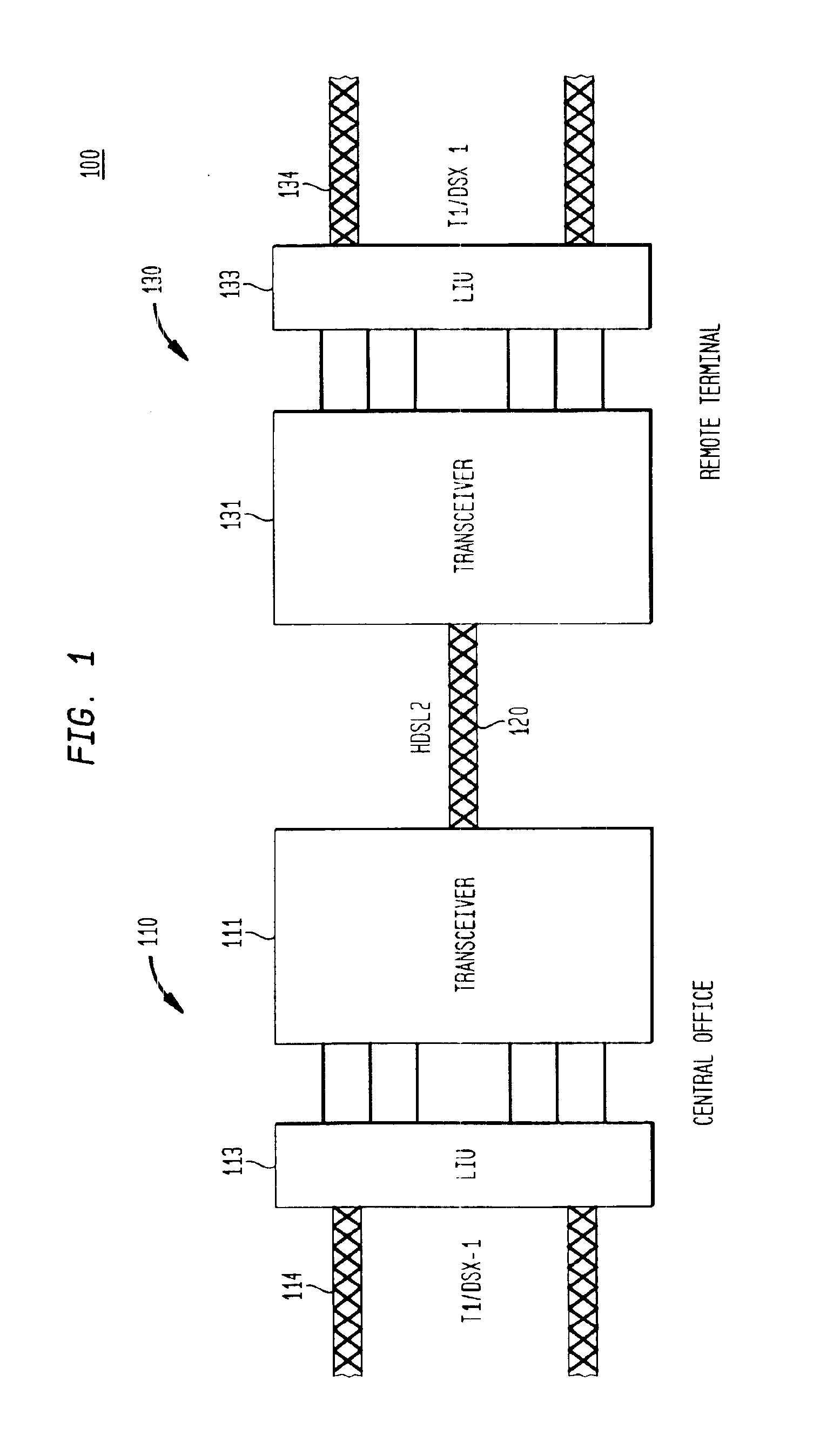
Referring initially to FIG. 1, illustrated is a system level diagram of an embodiment of a communications network, generally designated 100, within which an embodiment of a transceiver constructed according to the principles of the present invention may operate. The communications network 100 may form a portion of a larger communications network (e.g., the public switched telephone network) and may advantageously provide high-bit-rate digital subscriber line service over a single twisted pair wire (commonly referred to as HDSL2). The communications network 100 includes a central office 110 and a remote terminal 130. The central office 110 embodies any conventional or later developed switching system that facilitates communications over the communications network 100. The remote terminal 130 embodies any conventional or later developed communications device (e.g., a multimedia personal computer) adapted to communicate with the communications network 100. It should be understood that ...


PUM


Abstract

A filter circuit, method of configuring the filter circuit, and a bit pump and transceiver employing the circuit and method. In one embodiment, the filter circuit includes a noise prediction equalizer that generates a noise prediction equalizer coefficient during activation of the bit pump to reduce an intersymbol interference associated with a receive signal propagating along a receive path of the bit pump. The filter circuit also includes a decision feedback equalizer that generates a decision feedback equalizer coefficient during the activation of the bit pump to reduce the intersymbol interference associated with the receive signal. The noise prediction equalizer is concatenated with the decision feedback equalizer during showtime of the bit pump to form a precoder associated with a transmit path of the bit pump.

Description

TECHNICAL FIELD OF THE INVENTIONThe present invention is directed, in general, to digital signal processing and, more specifically, to a filter circuit for a bit pump and a transceiver employing the bit pump.BACKGROUND OF THE INVENTIONThe existing public switched telephone network represents a significant capital investment that has taken place in great part over the last 80 years. The public switched telephone network was originally designed for voice services (so-called plain old telephone service) and was entirely analog.Originally, the public switched telephone network included “local loops,” which connected homes and businesses to central office switches. This allowed anyone having a telephone connected to the central office switch to call one another. A given central office typically only covers a relatively small area.To allow people to call one another from greater distances, central office switches were interconnected by analog trunks. Unfortunately, signal quality suffered...

Claims


Application Information

Patent Timeline
IPC IPC(8): H03H7/30H04L25/03
CPCH04L25/03057H04L2025/03503
Inventor CHADHA, MANDEEP SINGHFU, ZHUOMCCASLIN, SHAWN R.VAN BAVEL, NICHOLAS R.
Owner LUCENT TECH INC
Learn More