Quality control device

Inactive Publication Date: 2005-04-12
KOENIG & BAUER AG
View PDF21 Cites 10 Cited by
  • Summary
  • Abstract
  • Description
  • Claims
  • Application Information

AI Technical Summary

Benefits of technology

With an appropriate layout of the pitch circle diameter of the chain wheel, of the drive transmission, as well as of the exterior diameter of the belt roller, the speed of the belt corresponds exactly to that of the chain. Thus, while being conveyed over the suction surface of the suction box, a sheet which is pulled by a gripper, remains at rest in relation to the belt, so that smearing is prevented. The pitch circle of the chain wheel, or the drive transmission, can also be slightly greater, so that the speed of the belt is slightly less than that of the gripper. This will insure that the sheet rests, tightly pulled and level, on the belt when the camera takes a picture. The difference between the speeds of the sheet and of the belt can be of an order of magnitude of a few percent. In every case, the relative displacement of the sheet and the belt in respect to each other, in the course of the mo

Problems solved by technology

Local interferences, with even running of the conveyance

Method used


Image

  • Quality control device
  • Quality control device
  • Quality control device

Examples


Embodiment Construction

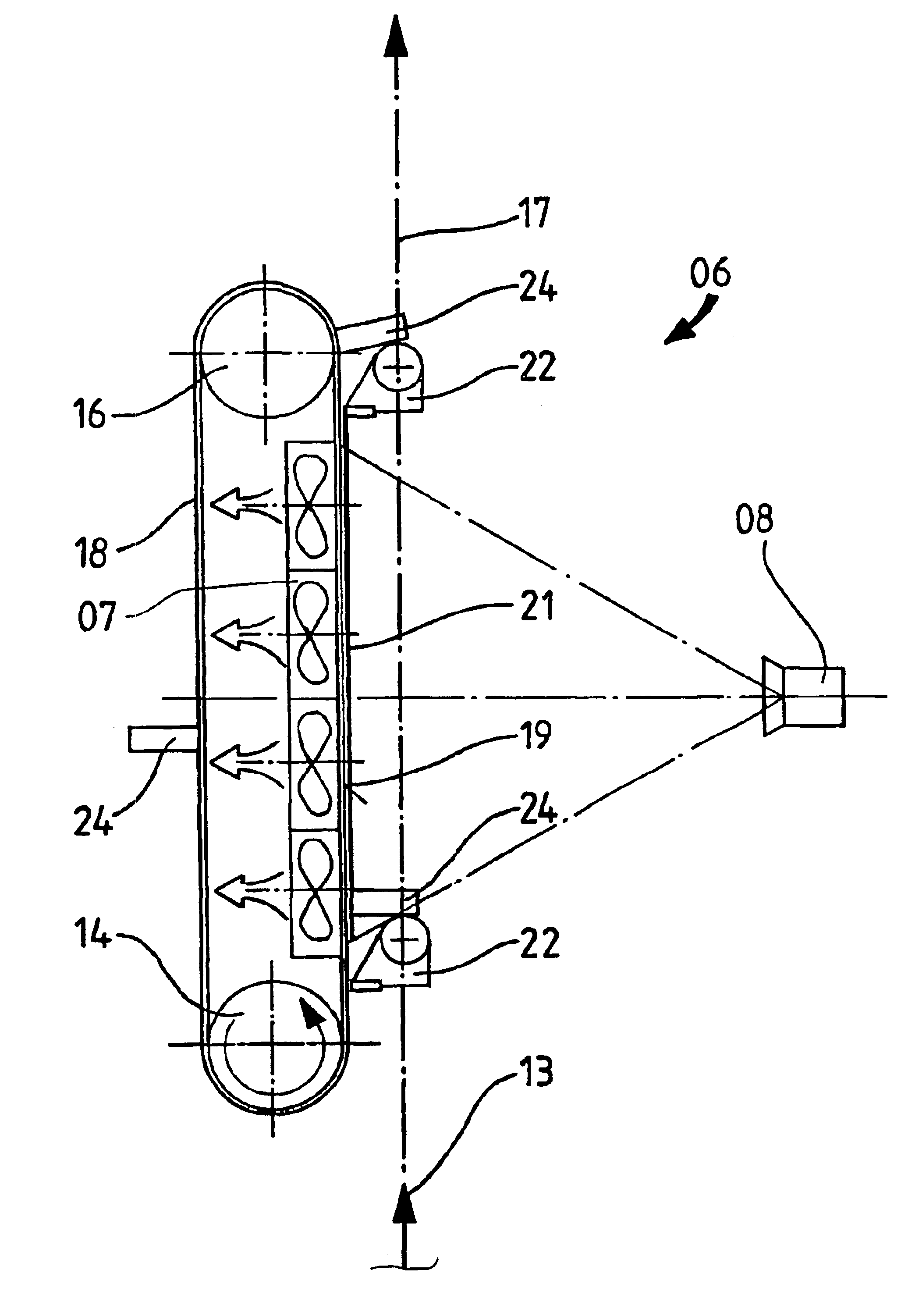
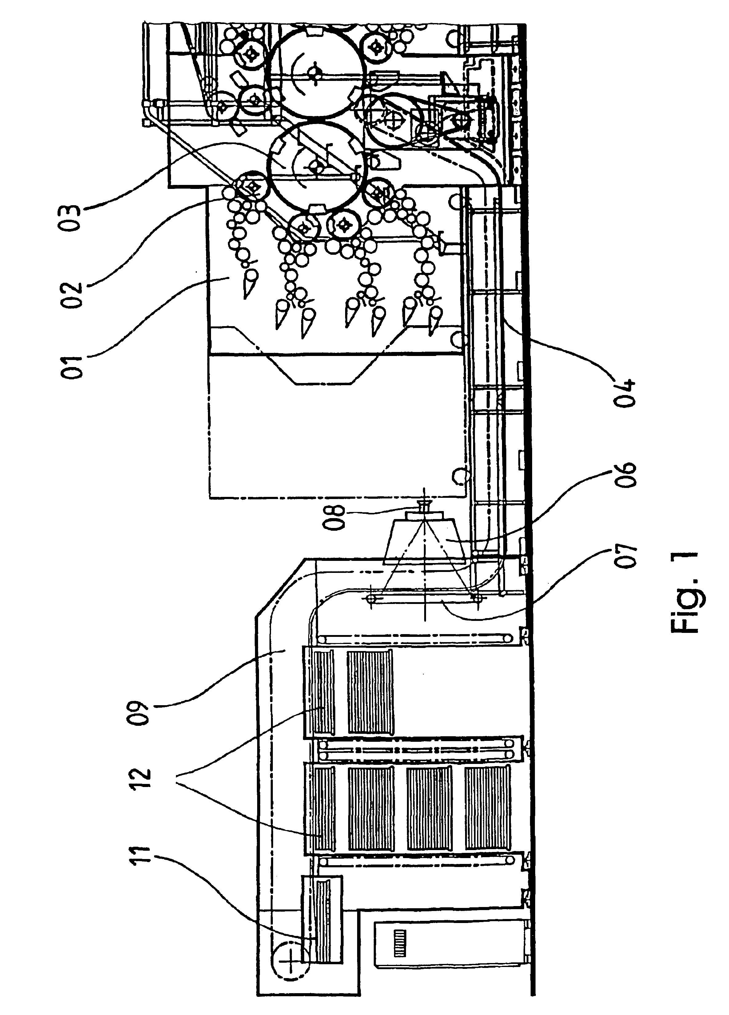
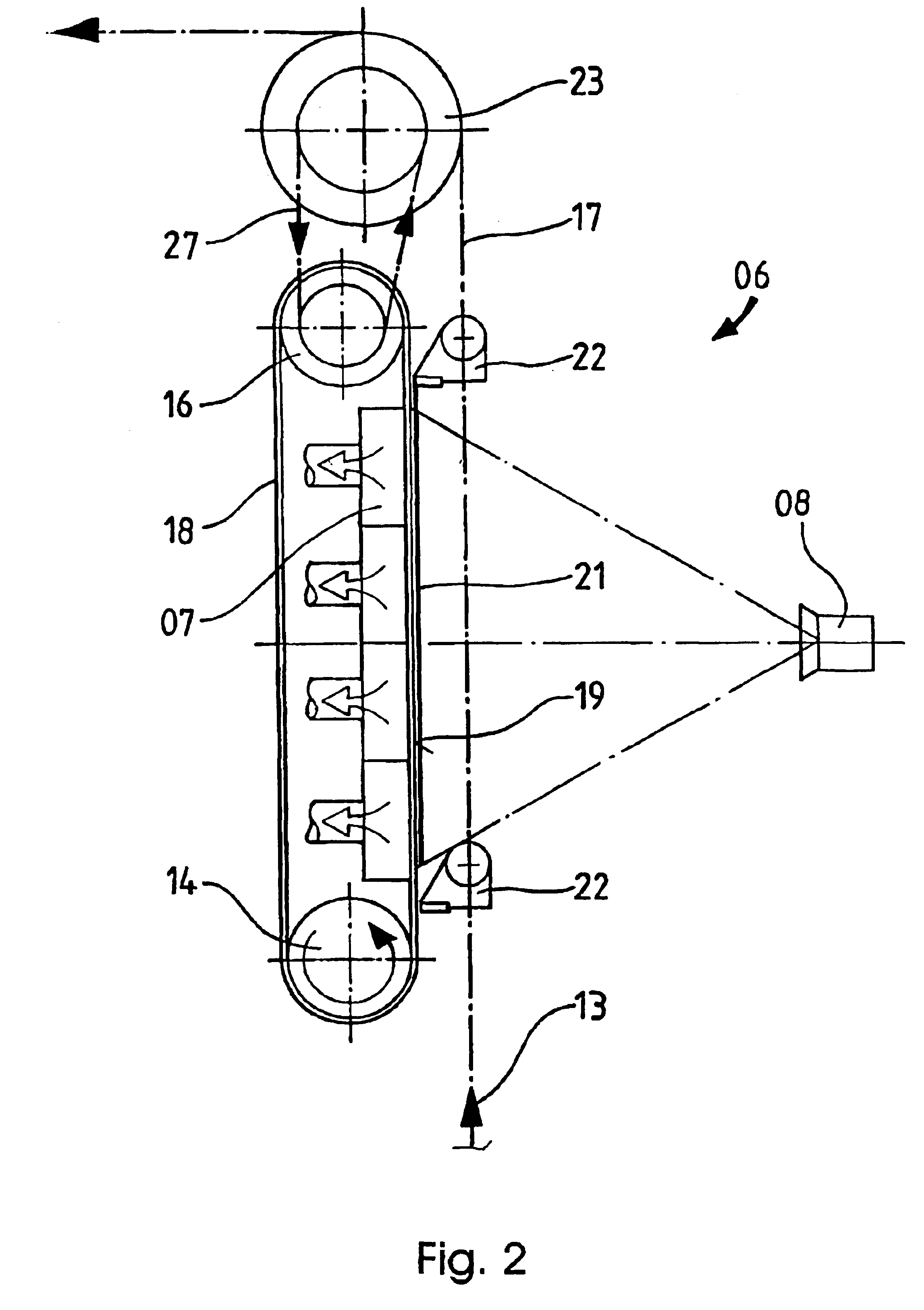
A schematic side elevation view through a sheet-fed rotary printing press having a quality control device is shown in FIG. 1. A sheet feeder of the rotary printing press is not represented in FIG. 1. The structure of a printing group, with inking systems 01 and plate cylinders 02, several of which are arranged on a collecting cylinder 03, is known per se and need not be described in greater detail here. Finished sheets, which have been imprinted on both sides, are taken over by a conveying track 04, which has a plurality of chain gripper systems 22 guided on an endless chain, for example grippers. 22. These chain gripper systems 22 are depicted schematically in FIGS. 2-4. The sheets are conducted on the grippers 22 through a quality control device 06, which includes a suction box 07, which suction box 07 is connected to a partial vacuum source, which is not specifically represented, as well as a CCD camera 08, whose field of view is directed onto the suction surface of the suction b...


PUM

PropertyMeasurementUnit
Thicknessaaaaaaaaaa
Forceaaaaaaaaaa
Speedaaaaaaaaaa

Abstract

A quality control device includes a suction box, at least one gripper which can be displaced along a suction surface of the suction box, and a CCD camera. A belt, which can be displaced in a sheet transport direction, is disposed on the suction surface of the suction box.

Description

FIELD OF THE INVENTIONThe present invention is directed to a quality control device of an imprinted sheet. A belt is used, in addition to a movable gripper, for pulling the sheet. The sheet conveying direction may be vertical.BACKGROUND OF THE INVENTIONA quality control device is known from EP 0 527 453 B1. Quality control devices of this type are employed in connection with printing presses for use in taking images of the imprinted sheets and for detecting deviations of those images from a desired print quality. This is accomplished by comparing these sheets with a desired printed image. It is desirable to be able to intervene correctively in the printing process when required.For this purpose, the above-described device has a suction box with a suction surface, over which suction surface the imprinted sheets are pulled with the aid of sheet grippers. Because of the frictional contact of the sheets with the suction surface of the suction box, it is assured that the sheets are alway...

Claims


Application Information

Patent Timeline
IPC IPC(8): B41F21/00B41F33/00B41F21/08B65H29/02B65H29/04B65H29/24B41F33/06B41F33/14B65H5/08G01N21/892
CPCB41F21/00B41F21/08B41F33/0036B65H29/041B65H29/242B65H29/044B65H2801/21B65H2301/3113B65H2301/542B65H2553/42
Inventor DUNNINGER, REINHOLDDUNNINGER, BRIGITTEREINHARD, GERALD JOSEF
Owner KOENIG & BAUER AG
Why Eureka
Try Eureka