
Lifting apparatus for a two-leaf folding flap

a two-leaf, folding technology, applied in the direction of applications, building components, door/window fittings, etc., can solve the problem of comparatively complex known lifting apparatus, and achieve the effect of simple construction

Inactive Publication Date: 2005-04-12
ARTURO SALICE
View PDF19 Cites 37 Cited by
  • Summary
  • Abstract
  • Description
  • Claims
  • Application Information

AI Technical Summary

Benefits of technology

It is the object of the invention to provide a lifting apparatus of the kind first mentioned which can be mounted in a space-saving manner with a simple construction and which ensures a guidance of the lower leaf in the manner that this does not come into contact with the end faces of body parts of the cupboard closed by the folding flap.
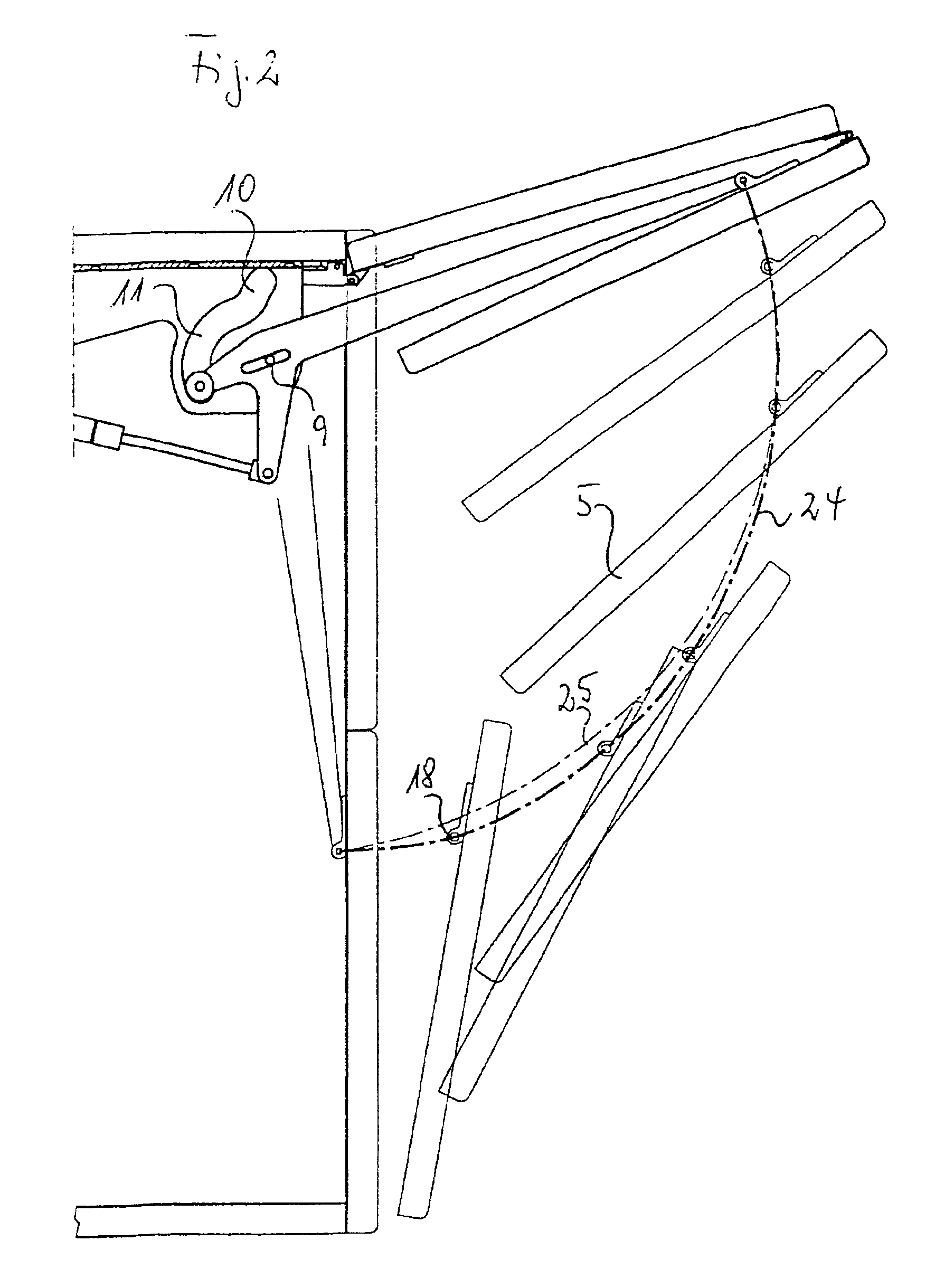
The lifting apparatus of the invention ensures a pivoting of the lower leaf of the folding flap in a form defined by the cam guide so that a coming into contact of the lower leaf with body parts of the cupboard is avoided during the opening movement or the closing movement. This defined guidance is achieved in a simple manner only by the double-armed lever which is controlled by its longitudinal displaceability on the pivot axis and its guiding in the cam guide. The lower leaf is expediently provided with a handle for the opening and closing of the folding flap. As a result of the guidance of the invention, no coming into contact of the lower leaf with body parts can be brought about even by improper pressure on this hand lever during opening and closing.

Problems solved by technology

This known lifting apparatus is, however, comparatively complex because special guide devices have to be provided for the lower region of the lower leaf of the folding flap.

Method used


Image

  • Lifting apparatus for a two-leaf folding flap
  • Lifting apparatus for a two-leaf folding flap
  • Lifting apparatus for a two-leaf folding flap

Examples


Embodiment Construction

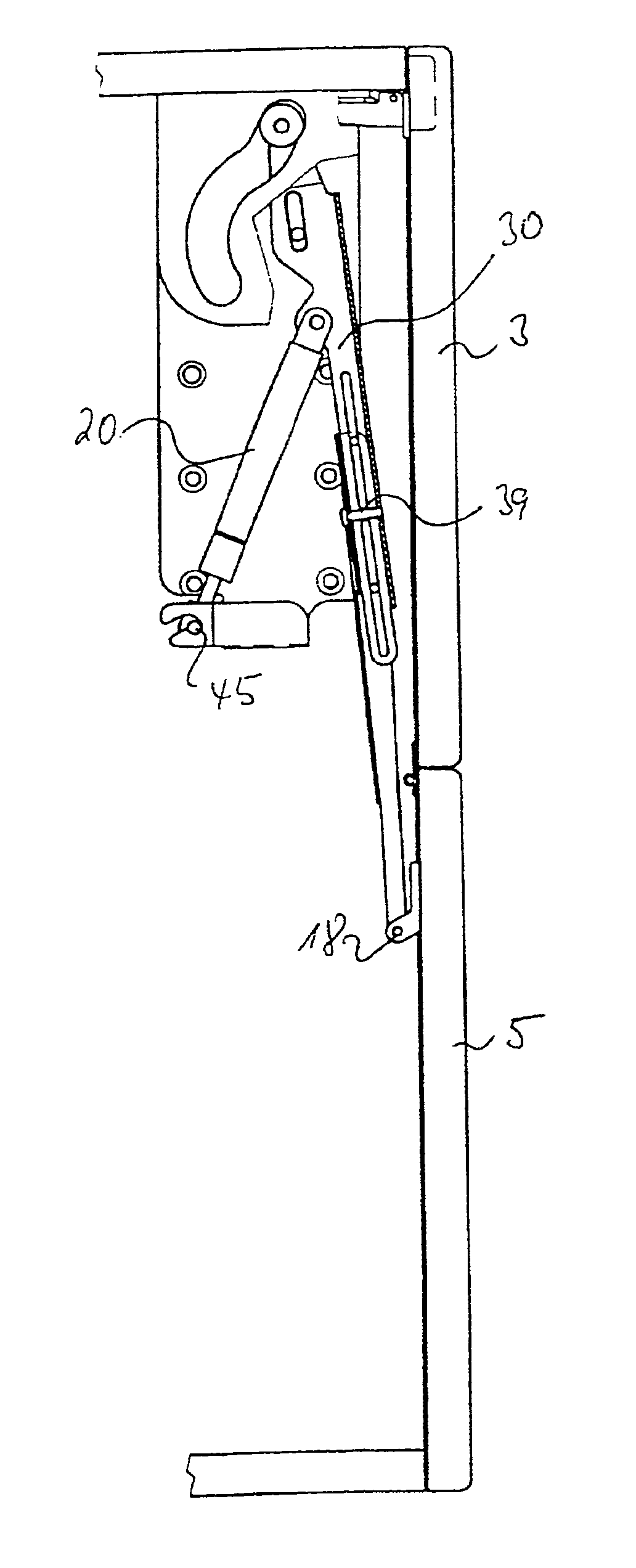
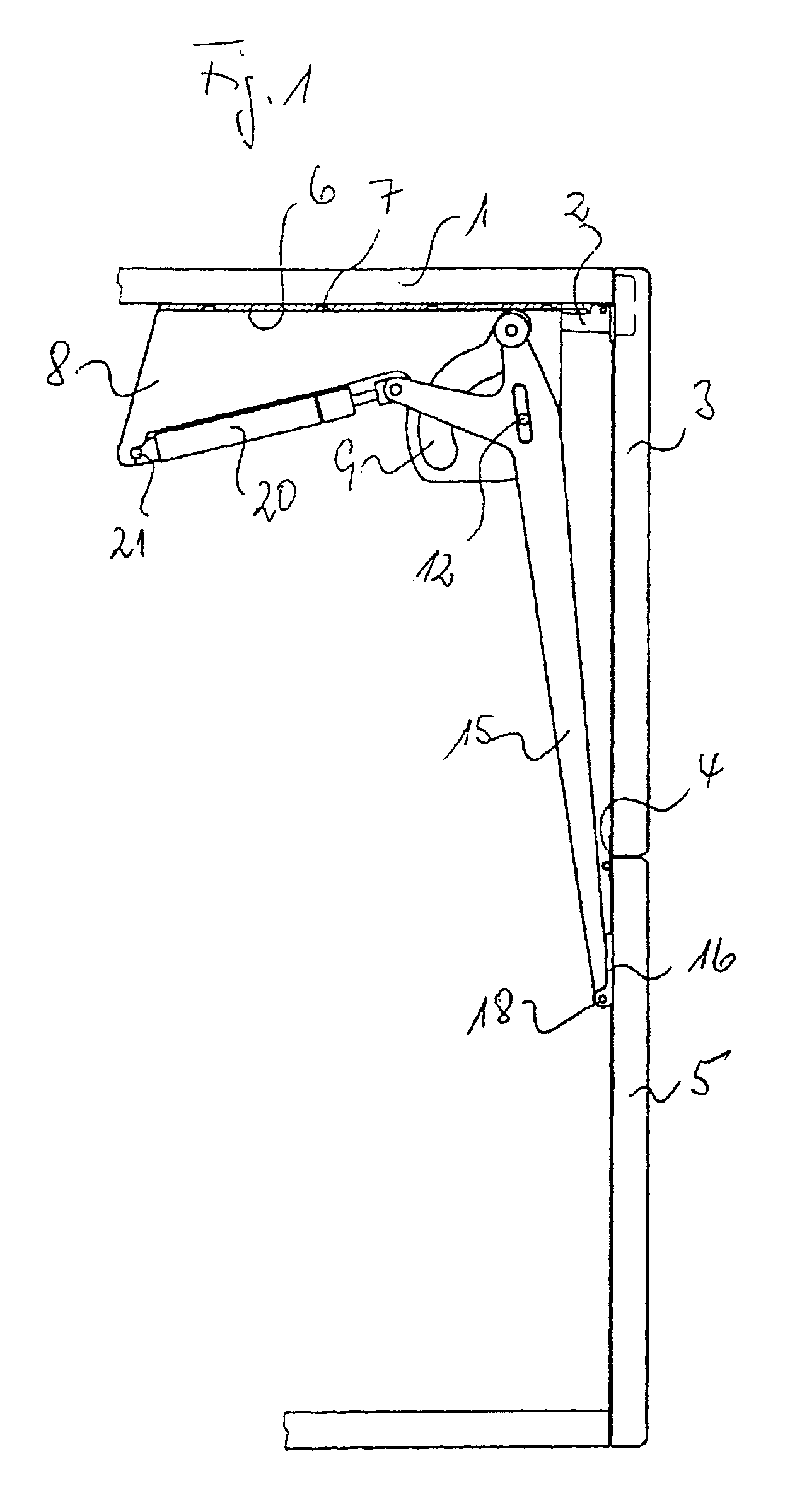
A side view of a cupboard or of a cupboard element or an element of a chest of drawers can be seen from FIG. 1, the opening of which is closed by a folding flap consisting of two linked leaves and of the front side wall of which is removed in order to make the lifting apparatus visible. The upper leaf 3 of a folding flap is hinged to the top wall 1 of the cupboard in the usual manner by two dual-link hinges 2 so that said folding flap is pivotable around a horizontal axis defined by the hinges 2. A lower leaf 5 is linked to the upper leaf 3 by a butt hinge 4. Assembly metal sheets 6 which are bent into a U shape and of which a centrally sectioned assembly metal sheet 6 is visible from FIG. 1, is screwed to the top wall 1 in the vicinity of the two side body parts of the cupboard. Each assembly metal sheet is provided with fastening boreholes 7 for fastening screws in its web part. The limb-like side parts 8 of the assembly metal sheet are provided with cam guides 9 which coincide in...


PUM


Abstract

A lifting apparatus for a two-leaf folding flap, whose upper leaf is hinged to a top or partition wall of a cupboard around a horizontal first axle and whose lower leaf is pivotally connected to the upper leaf around a second axle parallel to the first axle, comprises at least one two-armed lever which is pivotally mounted to a side body part around a horizontal pivot axle and whose longer arm is linked to the lower leaf. One end of the compressing spring element is pivotally connected to the body part and the other end is pivotally connected to the lever. To prevent the leaf from coming into contact with the end surfaces of body parts of the cupboard closed by the folding flap, the lever is guided in a longitudinally displaceable manner on its pivot axle and the shorter lever arm is guided in a cam guide fixed to the body via a slide block or a roller.

Description

BACKGROUND OF THE INVENTIONThe invention relates to a lifting apparatus for a two-leaf folding, flap whose upper leaf is hinged around a horizontal first axis at a top wall or partition wall of a cupboard and whose lower leaf is pivotally connected to the upper leaf around a second axis parallel to the first axis, consisting of at least one double-armed lever which is pivotally hinged around a horizontal pivot axis at a side body part of the cupboard and whose longer arm is linked to the lower leaf, and of a compression spring element whose one end is pivotally connected to the body part and whose other end is pivotally connected to the lever.In a lifting apparatus of this kind known from LU 55 310, the longer arm of the double-armed lever consists of two parts which can be telescoped relative to one another so that the lower leaf of the folding flap can come into contact with the end faces of the side body parts in its movement into the open position and into the closed position by...

Claims


Application Information

Patent Timeline
IPC IPC(8): E05F1/10E05F1/00E05D15/26E05F11/22E05D15/38E05D15/40
CPCE05D15/262E05F1/1091E05Y2900/20E05Y2201/416E05D15/38
Inventor SALICE, LUCIANO
Owner ARTURO SALICE
Learn More