Pellet feeding system for a molding machine

a molding machine and feeding system technology, applied in the field of feeding systems, can solve the problems of not addressing the supply of emc pellets, the system of this u.s. patent is quite complex, and the contamination of emc pellets is a source of contamination, so as to reduce the dust of emc, smooth the handling of pellets, and the effect of slowing down the movemen

Inactive Publication Date: 2005-04-12
ASM TECH SINGAPORE PTE LTD
View PDF8 Cites 29 Cited by
  • Summary
  • Abstract
  • Description
  • Claims
  • Application Information

AI Technical Summary

Benefits of technology

An advantage of the invention, in addition to the primary supply of the pellets (which generates EMC dust) being locatable outside the clean environment, is that the use of a suction means reduces the amount of such dust within the feeding system and which could be conveyed into the clean environment. Thus the invention provides a “clean” feeding system for the EMC pellets.
Preferably the buffer hopper includes an orifice for admission of air such that said conditions within the tube include an air flow from the buffer hopper to the outlet for slowing the movement of individual EMC pellets as they approach the buffer hopper after passing the outlet. This feature also assists in reducing EMC dust within the feeding system because it smoothes the handling of

Problems solved by technology

EMC pellets are a source of contamination in clean IC manufacturing environments because they can crumble and thus generate epoxy mould compound dust.
The system of this U.S. Patent however is quite complex because of the individualisation of the pellets at the supply-feed end and through to the

Method used


Image

  • Pellet feeding system for a molding machine
  • Pellet feeding system for a molding machine
  • Pellet feeding system for a molding machine

Examples


Embodiment Construction

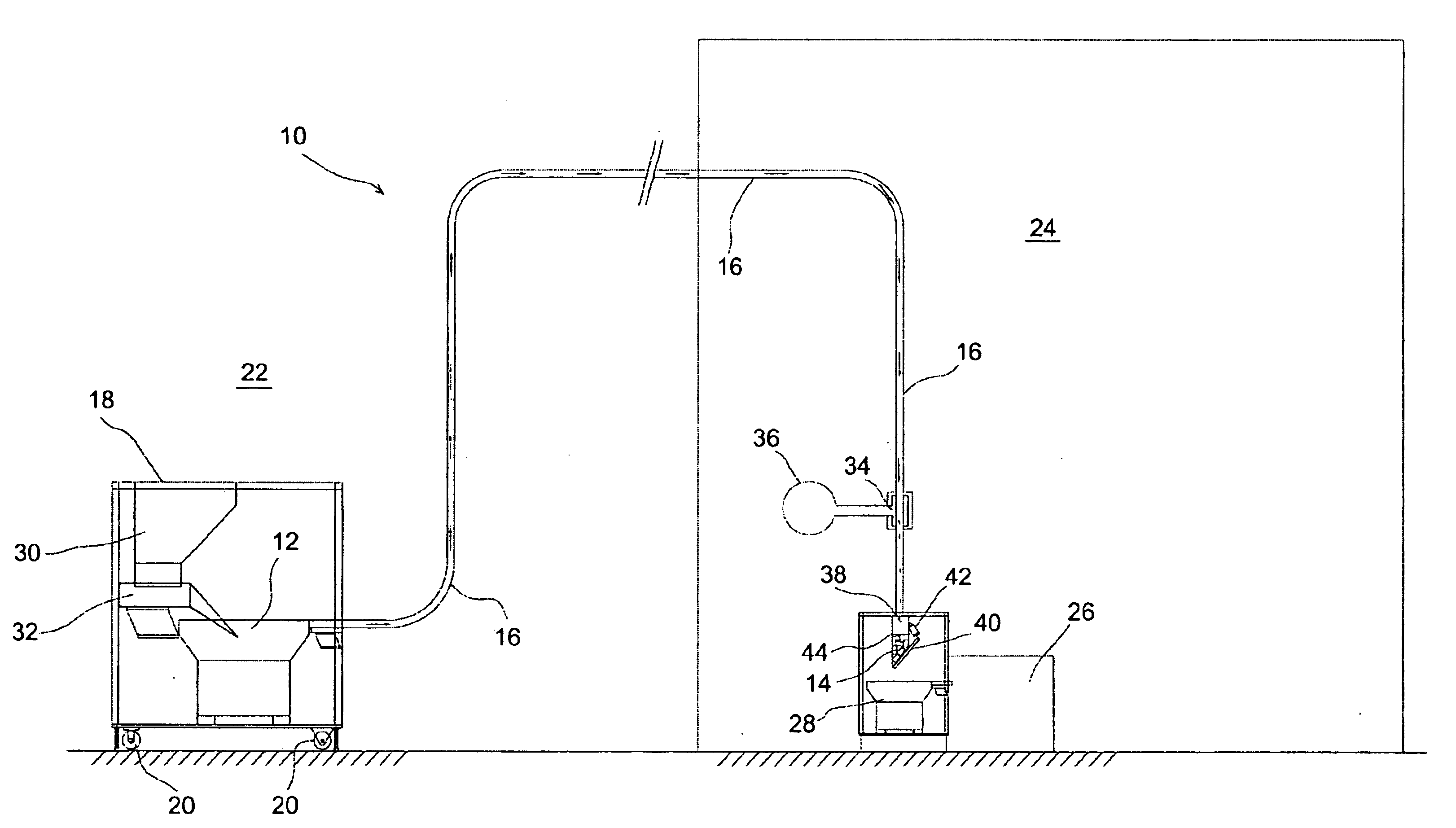
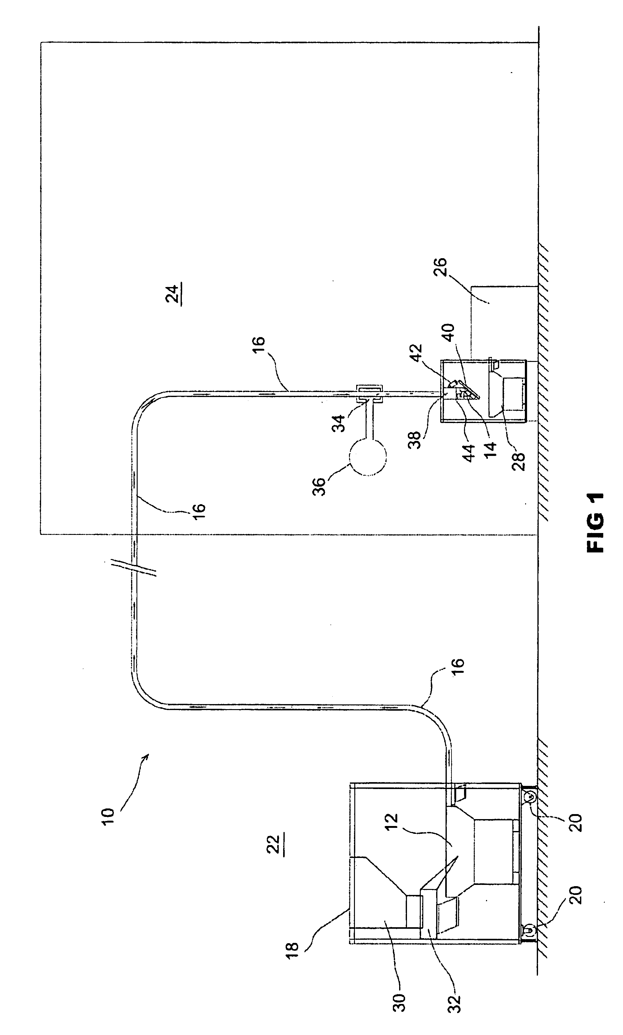
A feeding system 10 for EMC pellets comprises a supply 12 and a buffer hopper 14 interconnected by a tube 16 through which EMC pellets are transportable. The supply bowl 12 is part of a pellet supply apparatus 18 that is mobile per wheels 20 and is locatable in an environment 22 that is outside or remote from the clean environment 24 of a conventional automatic moulding machine 26. Machine 26 is preferably for encapsulation of IC devices. It includes a feeder bowl 28 over which the buffer hopper 14, in use of the feeding system 10, is located.

Pellet supply apparatus 18 includes a hopper 30 into which a stock of EMC pellets is loaded. A hopper feeder 32 feeds pellets from the hopper 30 and into the supply bowl 12.

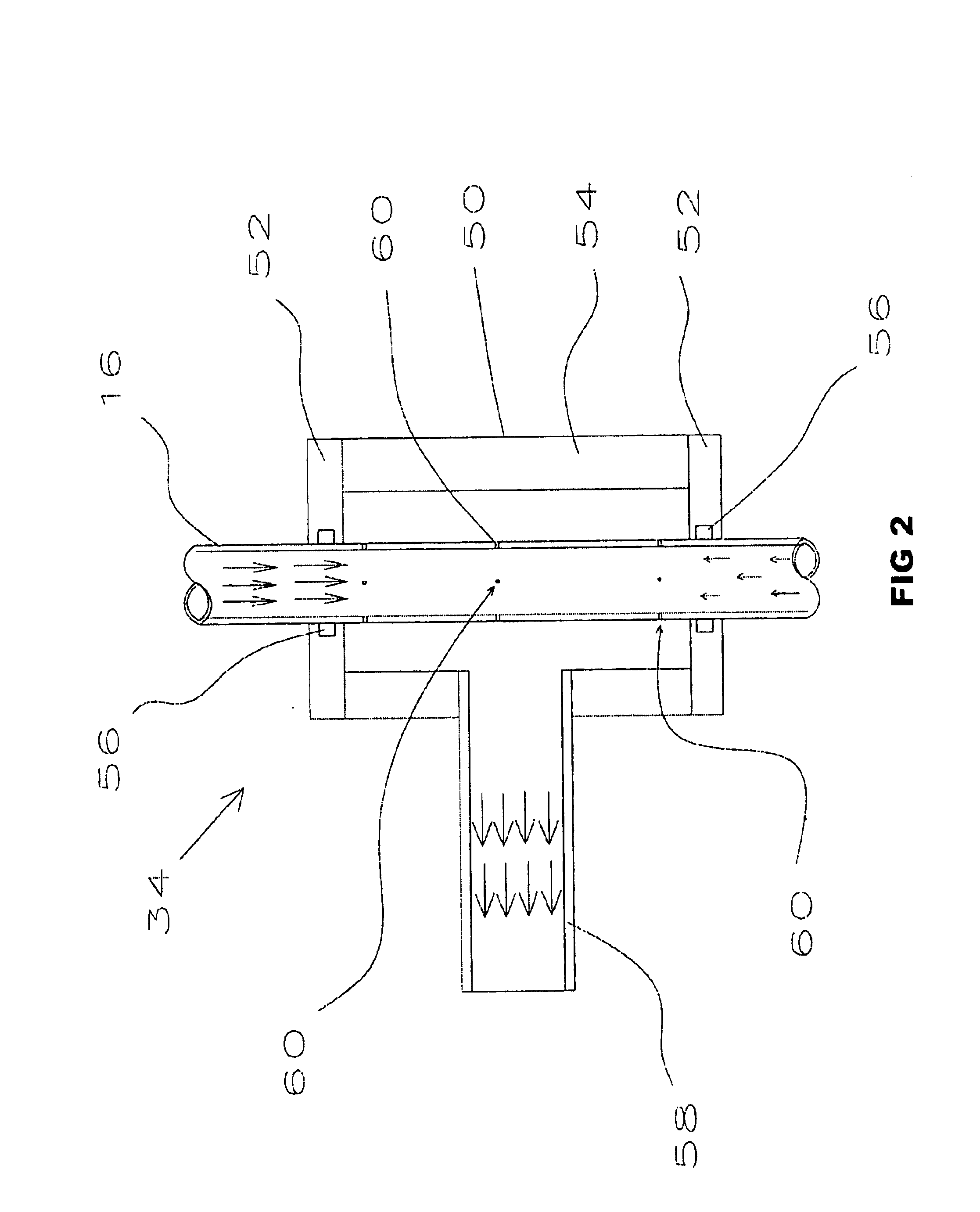
Tube 16 includes an outlet 34 which is proximate to the buffer hopper 14 end of the tube 16. Outlet 34 (see FIG. 2) comprises a housing 60, made up of end plates 62 and side wall 54, which surrounds tube 16 and is sealed relative thereto by seals 56 in the end plates 52. A c...


PUM

PropertyMeasurementUnit
Speedaaaaaaaaaa
Gravityaaaaaaaaaa
Vacuumaaaaaaaaaa

Abstract

A feeding system (10) for epoxy mould compound (EMC) pellets which has a supply bowl (12) situated outside the clean environment (24) of a conventional automatic moulding machine (26). A tube (16) extends from the supply bowl (12) to a buffer hopper (14) within the clean environment and which is located above the feeder bowl (28) of the automatic moulding machine (26). EMC pellets are transported through the tube (16) from the supply bowl (12) into the buffer hopper (14) via a vacuum suction system (34), (36) which is connected to the tube (16) in proximity to the buffer hopper (14). A counter air flow may be provided to slow the speed of the pellets as they enter the buffer hopper. Batches of the pellets accumulated in the buffer hopper (14) are periodically released into the feeder bowl (28) of the automatic moulding machine (26). The vacuum transportation system reduces dust from the pellets. Also productivity is increased compared to conventional use of the automatic moulding machine (26) by providing for the supply bowl (12) to have a significantly larger capacity compared to the feeder bowl (28) of the automatic moulding machine (28).

Description

TECHNICAL FIELDThe present invention relates to a feeding system for epoxy mould compound (EMC) pellets for an automatic moulding machine, for example for encapsulating integrated circuit (IC) packages.BACKGROUNDEMC pellets are a source of contamination in clean IC manufacturing environments because they can crumble and thus generate epoxy mould compound dust. It is highly desirable therefore to locate an EMC pellet supply or a moulding machine as much as possible outside the clean environment of the machine so as to reduce the amount of epoxy mould compound dust that may be generated within that environment from such pellets.Thus U.S. Pat. No. 5,656,305 (Venrooij), for example, discloses a system for dosed conveying and selecting of pellets for a moulding apparatus for lead frames in which a supply-feed device and in-feed and selection device of the system are located in a housing in order to obtain a separation between a high dust level and a low dust level environment. This syste...

Claims


Application Information

Patent Timeline
IPC IPC(8): B29C31/00B29C31/02
CPCB29C31/02B29K2063/00
Inventor HO, SHU CHUENKUAH, TENG HOCKLIU, JIE
Owner ASM TECH SINGAPORE PTE LTD
Why Eureka
Try Eureka