Mixed flow turbine and mixed flow turbine rotor blade

a technology of mixed flow turbine and rotor blade, which is applied in the direction of liquid fuel engines, vessel construction, marine propulsion, etc., can solve the problems of deteriorating response ability of acceleration, weak acceleration power of the turbine, and reduced turbine efficiency. achieve the effect of low theoretical velocity ratio and high efficiency

Inactive Publication Date: 2005-04-12
MITSUBISHI HEAVY IND LTD
View PDF4 Cites 35 Cited by
  • Summary
  • Abstract
  • Description
  • Claims
  • Application Information

AI Technical Summary

Benefits of technology

Therefore, an object of the present invention is to provide a mixed flow turbine and a mixed flow turbine rotor blade which can be operated at high efficiency at a low theoretical velocity ratio.

Problems solved by technology

By increasing the supply of fuel, although one expects the rise of the number of the rotation, the turbine efficiency reduces actually and the acceleration power of the turbine becomes weak and the response ability of the acceleration is deteriorated.
As a result, the turbine must be operated in the low efficiency point B.

Method used


Image

  • Mixed flow turbine and mixed flow turbine rotor blade
  • Mixed flow turbine and mixed flow turbine rotor blade
  • Mixed flow turbine and mixed flow turbine rotor blade

Examples


Embodiment Construction

Hereinafter, a mixed flow turbine of the present invention will be described with reference to the attached drawings.

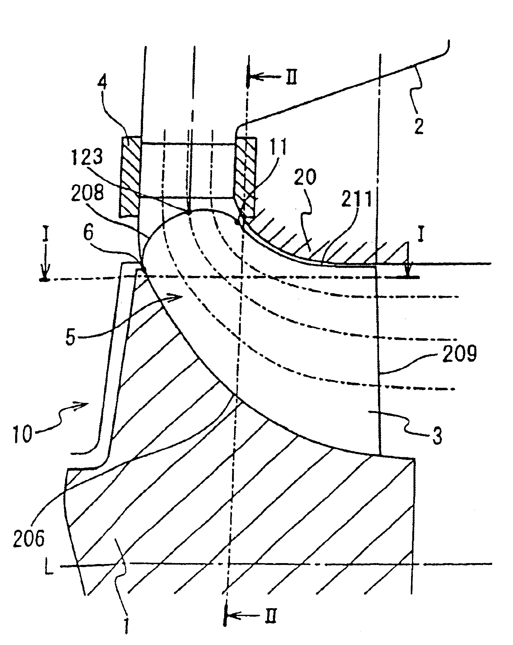
In FIGS. 7A to 7C, the mixed flow turbine according to an embodiment of the present invention is composed of a rotation blade unit 10, a nozzle 4 and a scroll 2.

The scroll 2 is fixed to a fixed shroud 20. A nozzle 4 is interposed between the scroll 2 and the rotation region of the rotor blades 3.

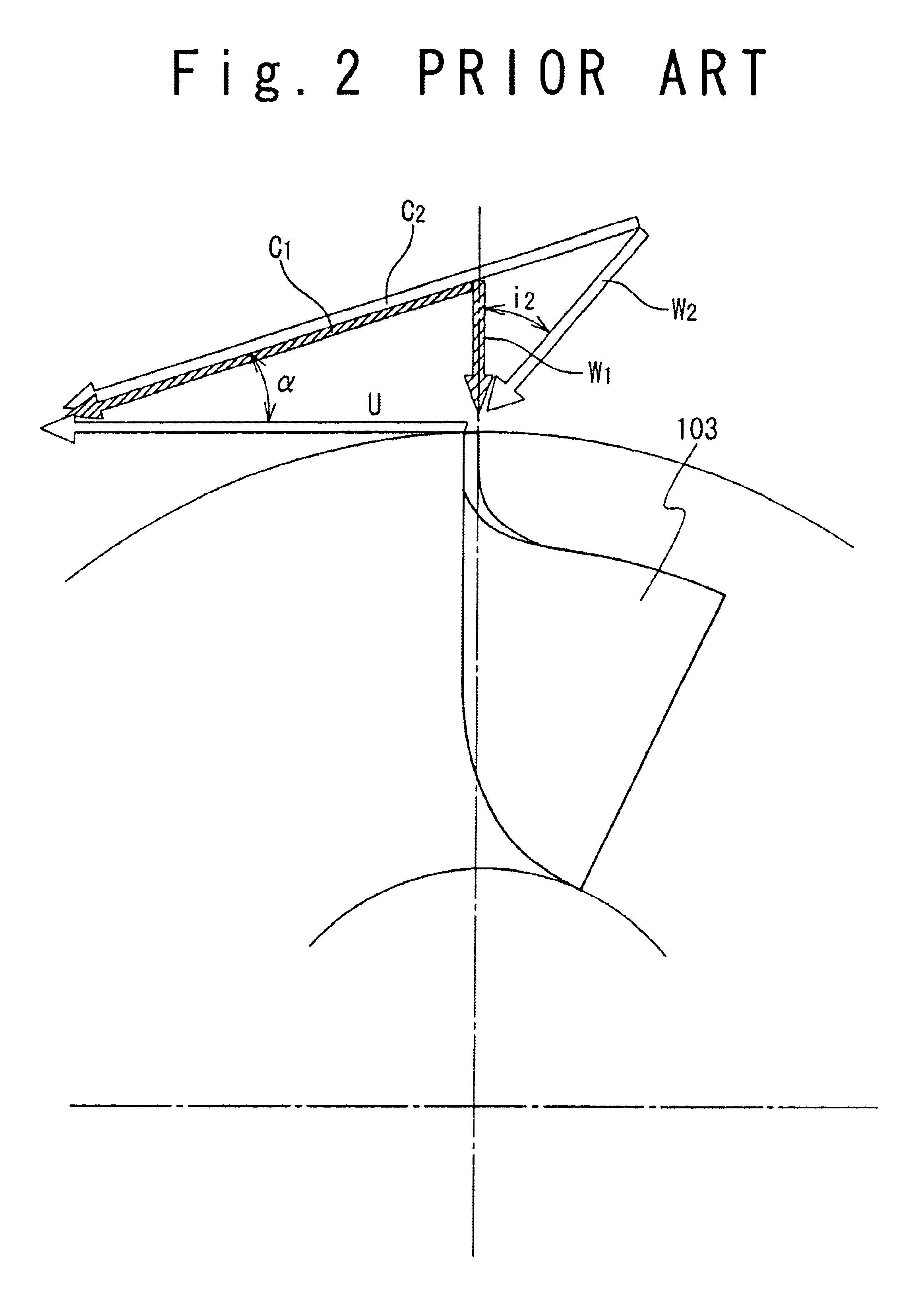
The nozzle 4 gives absolute velocity indicated in the above-mentioned velocity triangle shown in FIG. 2 to the fluid supplied from the scroll 2, and supplies the fluid to the rotation region of the rotor blade 3.

The rotor blade unit 10 includes a plurality of blades 3 which are arranged around and fixed to a hub 1. The rotor blade 3 has an inner side edge 206, an outer side edge 211, a gas inlet side edge 208 and an outlet side edge 209. The inner side edge 206 is fixed to the surface of the hub 1. The outer side edge 211 is rotated around a rotation axis along the inner curve...


PUM


Abstract

A mixed flow turbine includes a hub attached to a rotation axis and a plurality of rotor blades. Each of the plurality of rotor blades is attached to the hub in a radial direction, and the hub is rotated based on fluid supplied to a rotation region of the plurality of rotor blades. Each of the plurality of rotor blades has a curved shape that convexly swells on a supply side of the fluid.

Description

BACKGROUND OF THE INVENTION1. Field of the InventionThe present invention relates to a mixed flow turbine and a mixed flow turbine rotor blade.2. Description of the Related ArtAs a machine which converts combustion gas energy into mechanical rotation energy efficiently, a radial turbine is known. FIG. 1A is a horizontal cross sectional view of a rotor blade 103 of the radial turbine, and FIG. 1B is a vertical cross sectional view of a rotor blade unit 100 of the radial turbine.As shown in FIG. 1B, the radial turbine is provided with the rotor blade unit 100 attached to a rotation axis and a scroll 102 having a shape similar to a snail. The rotor blade unit 100 has a hub 101 and a plurality of blades 103 arranged on the hub 101 in a radial direction. A nozzle 104 is interposed between the scroll 102 and a rotating region of the blades 103.A gas flows from the scroll 102 into the nozzle 104, and is accelerated and given rotation force by the nozzle 104 to produce high velocity flow 10...

Claims


Application Information

Patent Timeline
Patent Type & Authority Patents(United States)
IPC IPC(8): F01D5/14F01D5/04
CPCF01D5/14
Inventor HIGASHIMORI, HIROTAKAYOKOYAMA, TAKAOMIKOGAMI, TAKASHIYOSHIDA, SHIRO
Owner MITSUBISHI HEAVY IND LTD
Why Eureka
Try Eureka