Power distribution control apparatus and control method

a control apparatus and power distribution technology, applied in the direction of gearing, instruments, tractors, etc., can solve the problems of difficulty in coordinating the manually inputted differential limiting torque with the proper torque, and the differential limiting torque must be properly changed, so as to achieve optimal maneuverability

Inactive Publication Date: 2005-04-12
SUBARU CORP
View PDF11 Cites 15 Cited by
  • Summary
  • Abstract
  • Description
  • Claims
  • Application Information

AI Technical Summary

Benefits of technology

It is an object of the present invention to provide a vehicular power distribution control apparatus capable of realizing an optimum maneuverability suitable for traveling conditions and road conditions while reflecting the intention of a driver.

Problems solved by technology

However, in order to realize a vehicle maneuverability as intended by a driver, the differential limiting torque must be properly changed according to road conditions or miscellaneous traveling conditions.
Accordingly, it is difficult to coincide the manually inputted differential limiting torque with a proper torque in order to obtain an optimum maneuverability.

Method used


Image

  • Power distribution control apparatus and control method
  • Power distribution control apparatus and control method
  • Power distribution control apparatus and control method

Examples


Embodiment Construction

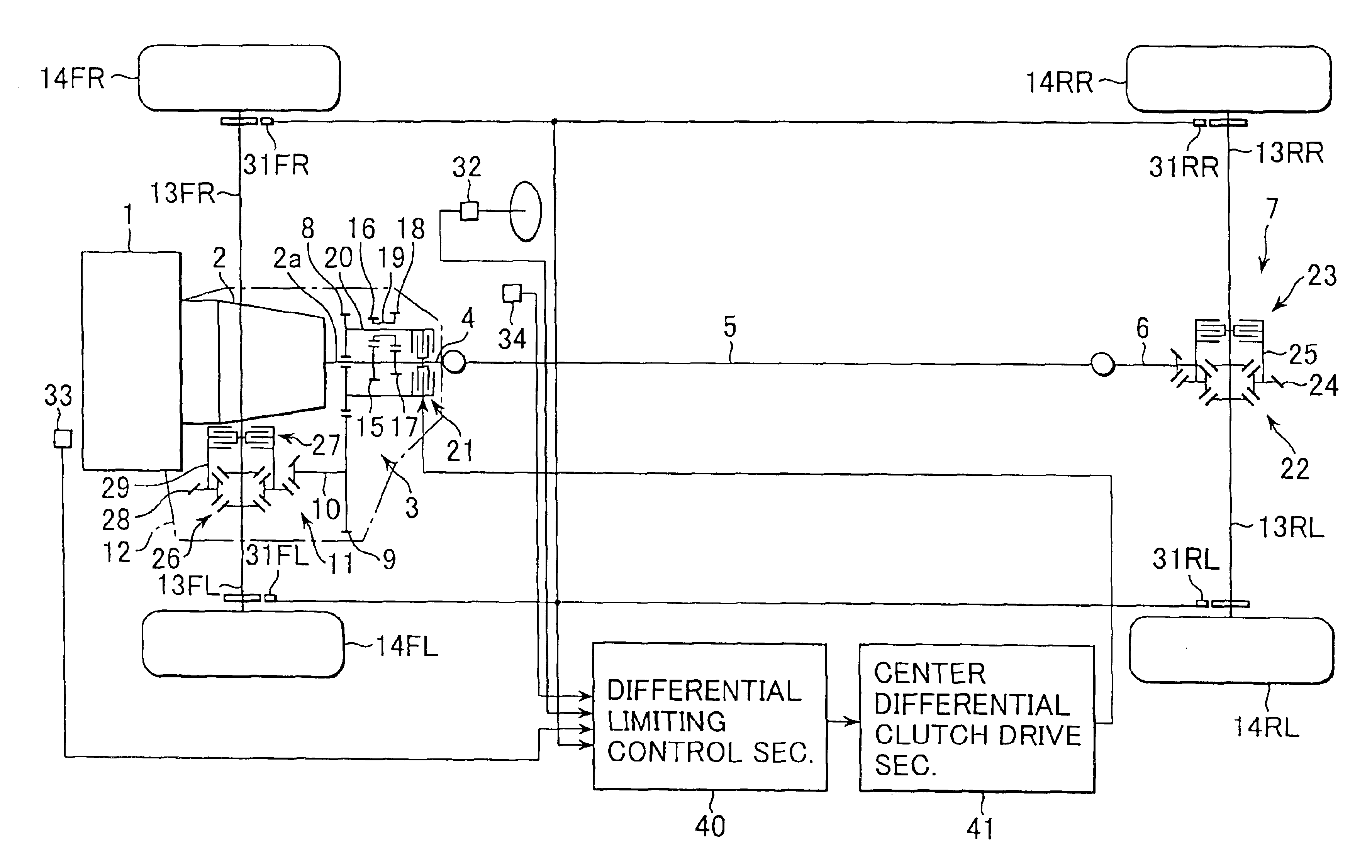
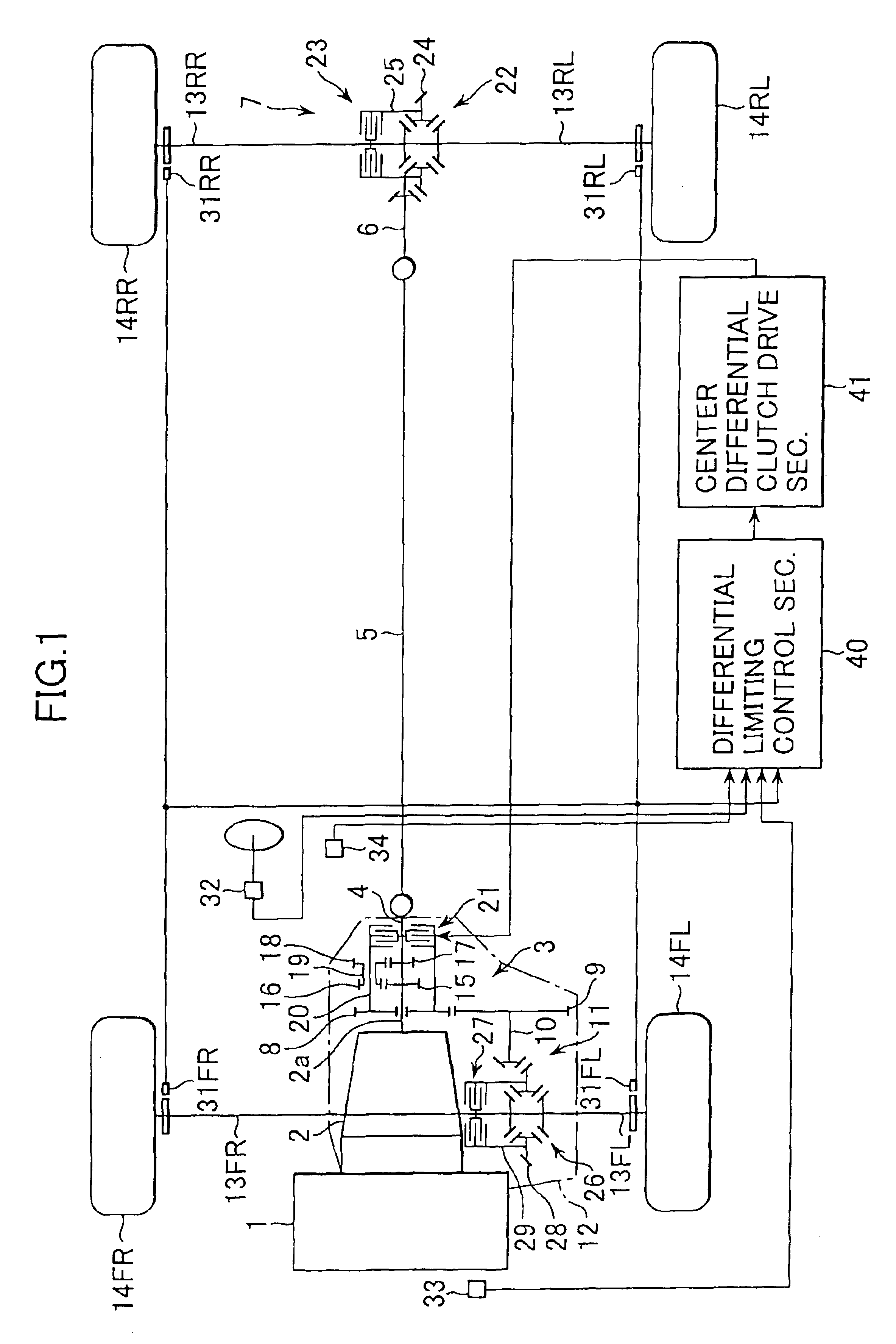
Referring now to FIG. 1, reference numeral 1 denotes an engine mounted on a front part of a vehicle. Driving force of the engine 1 is transmitted to a center differential 3 through an automatic transmission 2 (including a torque converter) and a transmission output shaft 2a. Further, the driving force of the engine 1 inputs from the center differential 3 to a rear final reduction gear unit 7 through a rear drive shaft 4, a propeller shaft 5 and a drive pinion 6 and on the other hand the driving force inputs from the center differential 3 to a front final reduction gear unit 11 through a transfer drive gear 8, a transfer driven gear 9 and a front drive shaft 10. The automatic transmission 2 is accommodated integrally with the center differential 3 and the front final reduction gear unit 11 in a casing 12.

The driving force inputted to the rear final reduction gear unit 7 is transmitted to a rear left wheel 14RL and a rear right wheel 14RR through a rear left drive shaft 13RL and a rea...


PUM


Abstract

In a differential limiting torque control section, a target differential rotation speed between front and rear drive shafts is established according to a dial position inputted by a driver of a variable dial. Further, an actual differential rotation speed between front and rear drive shafts is calculated and a deviation between the target differential rotation speed and the actual differential rotation speed is calculated. Based on the deviation, a first differential limiting torque and based on a dial position of a variable dial a second differential limiting torque are calculated. Further, a third differential limiting torque is calculated based on the dial position and a throttle opening angle. A final differential limiting torque between front and rear drive shafts is obtained by summing up these first, second and third differential limiting torques.

Description

BACKGROUND OF THE INVENTION1. Field of the InventionThe present invention relates to a vehicular power distribution control apparatus and control method and more particularly to a control apparatus and method for controlling driving force to be transmitted from one drive shaft to the other drive shafts.2. Discussion of Related ArtsGenerally, the power distribution control between front and rear wheels for four-wheel drive vehicles or the power distribution control between left and right wheels are performed by variably controlling an engagement force, namely a differential limiting torque, of a hydraulically operated multiple-disc friction clutch and the like. The differential limiting control produces a large change in a vehicle maneuverability, depending upon its control characteristic. Further, in case of the differential limiting control having identical control logics and control constants, the maneuverability of a vehicle also varies according to the aged deterioration of tire...

Claims


Application Information

Patent Timeline
Patent Type & Authority Patents(United States)
IPC IPC(8): B60K23/08B60K23/04B60K17/35B60K17/346B60W50/00
CPCB60K23/0808B60K17/3462B60K17/35B60K23/04B60T2201/14B60W2050/0063Y10T477/735B60W2710/027B60W2720/28Y10T477/613Y10T477/755Y10T477/606B60W2710/025B60W2050/001B60W30/18145
Inventor MATSUNO, KOJI
Owner SUBARU CORP
Why Eureka
Try Eureka