Analytical element and measuring device and substrate quantification method using the same

a technology of analytic elements and measuring devices, applied in the direction of enzymology, biomass after-treatment, liquid/fluent solid measurement, etc., can solve the problems of poor accuracy, affecting a large extent, and all poorly specific to sugars

Inactive Publication Date: 2005-04-12
PHC HLDG CORP
View PDF21 Cites 122 Cited by
  • Summary
  • Abstract
  • Description
  • Claims
  • Application Information

AI Technical Summary

Problems solved by technology

These methods, however, are all poorly specific to sugars and hence have poor accuracy.
Among these methods, the polarimetry is simple in manipulation, but is largely affected by the temperature during the manipulation.
Therefore, the polarimetry is not suitable as a method for simple quantification of sugars at home, etc. for ordinary people.
However, as speculated from the reaction process, there is a drawback that the measurement results are largely affected by the oxygen concentration of the sample, and if the oxygen is absent in the sample, the measurement is infeasible.
In the above-mentioned conventional biosensors, even after introduction of the sample into the biosensor, part of the sample is exposed to outside, and part of the sample therefore evaporates during the measurement, possibly causing a change in substrate concentration of the sample.
However, with the reduction of the sample, even a slight change in substrate concentration may cause variations in measured values in the conventional biosensors.

Method used


Image

  • Analytical element and measuring device and substrate quantification method using the same
  • Analytical element and measuring device and substrate quantification method using the same
  • Analytical element and measuring device and substrate quantification method using the same

Examples


example 1

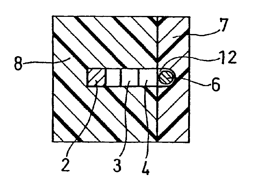
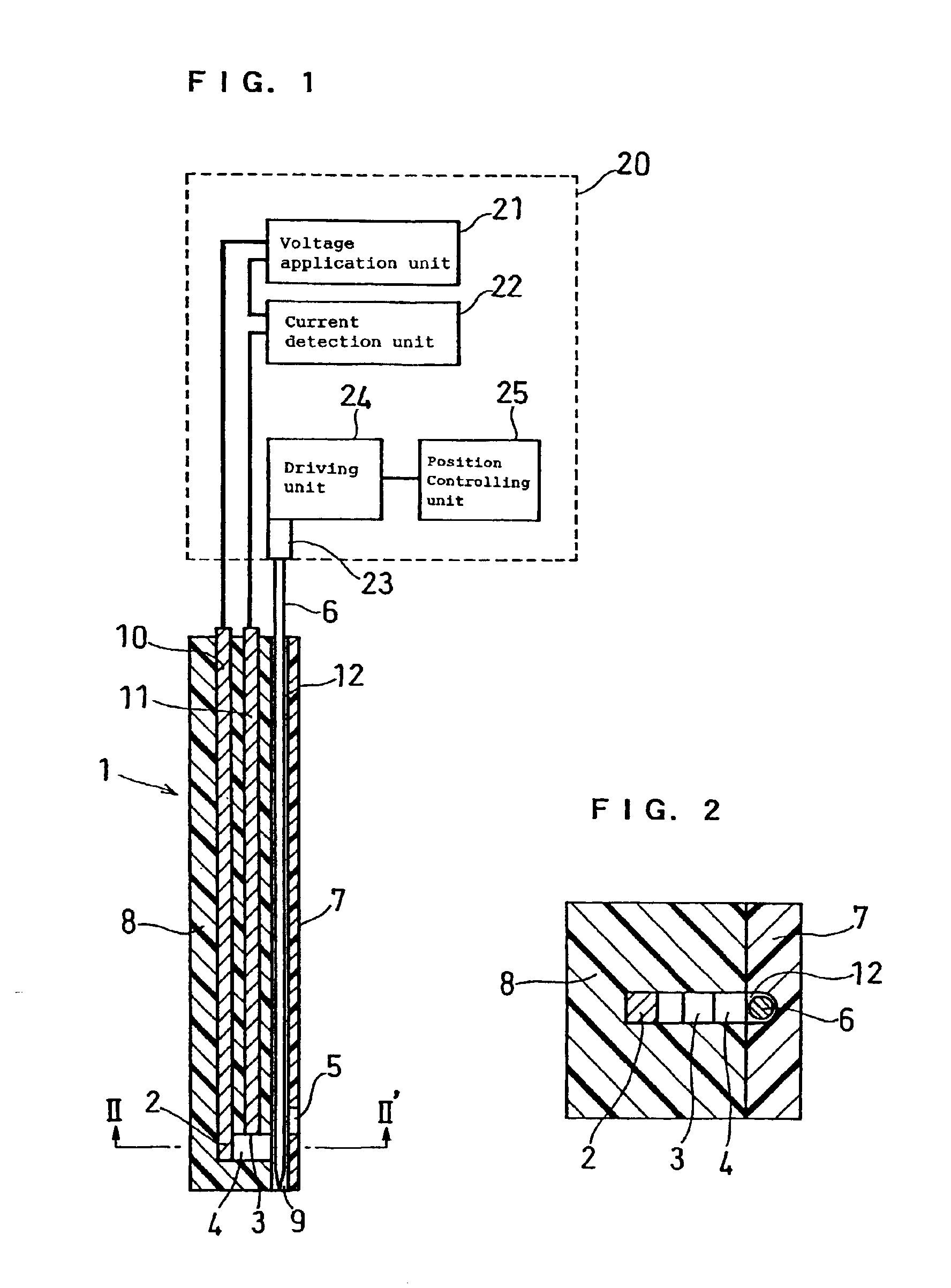
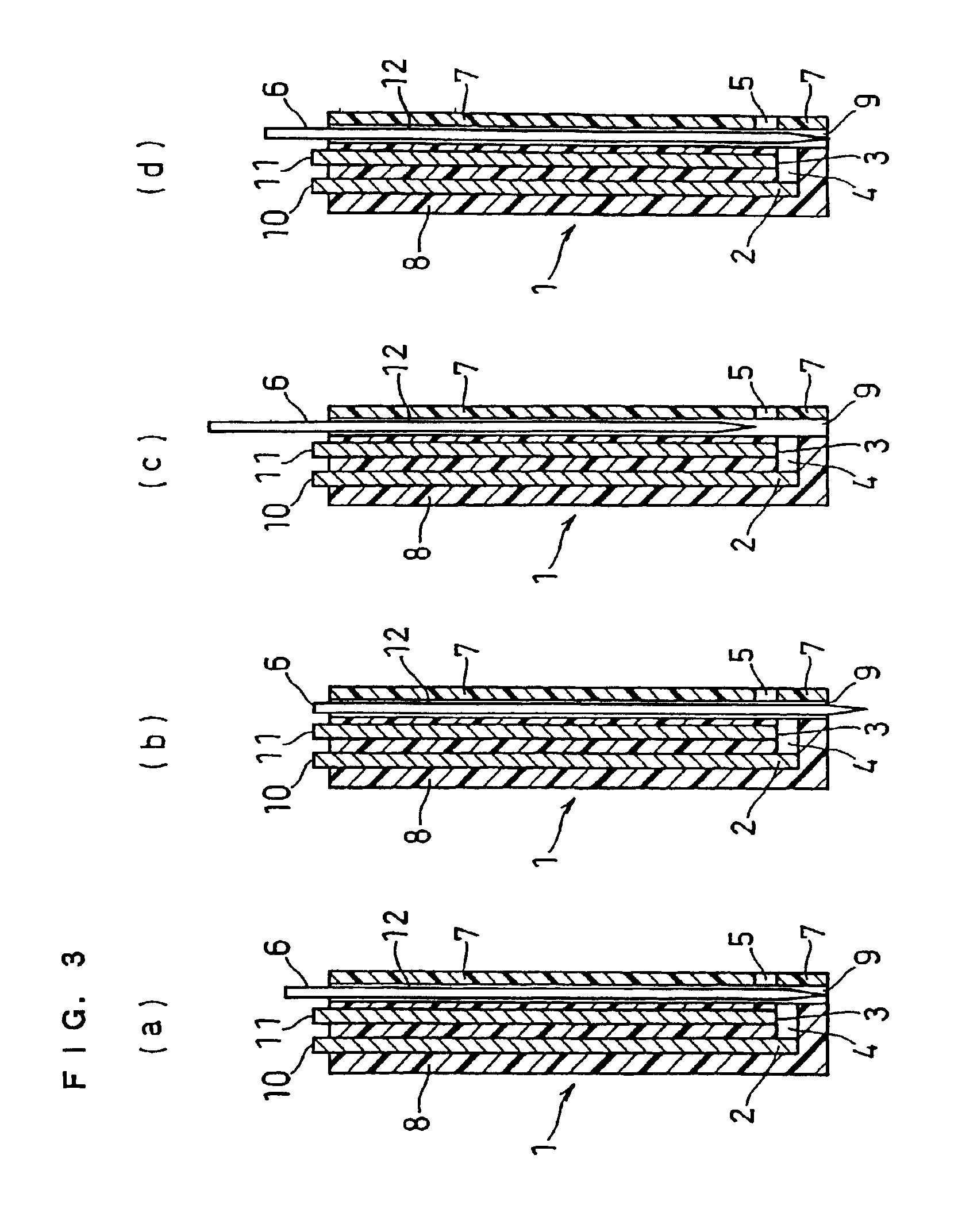
FIG. 1 is a schematic view of a measuring device used in this example and is a longitudinal cross-sectional view of an analytical element from which the reagent layer and surfactant layer are omitted. FIG. 3 is a longitudinal cross-sectional view showing the operation of a puncture member in the analytical element, and, FIGS. 4 to 5 are longitudinal cross-sectional views showing other forms of electrodes in the analytical element of this example from which the regent layer and surfactant layer are omitted.

The measuring device as shown in FIG. 1 is composed of an analytical element 1 and a main body 20. The analytical element 1 is composed of a puncture member 6, a rod-like member 8 and a cover 7. The rod-like member 8 comprises a cavity 4 for accommodating a sample, a working electrode 2 and a counter electrode 3 exposed to the inside of the cavity 4, and a reagent layer (not shown in the figure) carried inside the cavity 4. The cover 7 is joined to the rod-like member 8 so as to co...

example 2

An analytical element of this example will be described with reference to FIG. 8 and FIG. 9. FIG. 8 is a longitudinal cross-sectional view of the analytical element of this example, and FIG. 9 is an exploded perspective view of the same analytical element from which the reagent layer and surfactant layer are omitted.

First, a silver paste is printed on an electrically insulating base plate 31 made of polyethylene terephthalate by screen printing to form a working electrode lead 32 and a counter electrode lead 33. Then, a conductive carbon paste containing a resin binder is printed on the base plate 31 to form a working electrode 34. The working electrode 34 is in contact with the working electrode lead 32. Further, an insulating paste is printed on the base plate 31 to form an insulating layer 36. The insulating layer 36 covers the outer periphery of the working electrode 34 so as to keep the exposed area of the working electrode 34 constant. Thereafter, a conductive carbon paste con...

example 3

FIG. 10 is a perspective view of an analytical element used in this example.

The analytical element of this example is composed of a base plate 51 having the same constitution as that of the base plate 31 of Example 2, a spacer 54, a mid cover 56 covering the spacer, a top cover 58, and a stopper 57. The spacer 54 has an depression 55 which is open at its both sides and bottom face, and the depression forms a cavity for accommodating a sample in combination with the base plate 51. The depression 55 of the spacer has openings 55a and 55b at its sides, and one of the openings serves as the sample supply port and the other serves as the air vent. The base plate 51 has a working electrode and a counter electrode connected to leads 52 and 53, respectively. These electrodes are exposed to the depression 55 of the spacer 54. The top cover 58 moves in parallel with the electrode-printed surface of the base plate 51 along grooves formed in the stopper 57.

After a sample is supplied from the op...


PUM

PropertyMeasurementUnit
sizeaaaaaaaaaa
lengthaaaaaaaaaa
diameteraaaaaaaaaa

Abstract

The present invention provides an analytical element which is free from evaporation of a sample during measurement and therefore capable of quantifying a substrate using a very small amount of sample with high accuracy and which is free from scattering of the sample during and after the measurement and therefore hygienically excellent; and a measuring device and a substrate quantification method using the same. The analytical element comprises a cavity for accommodating a sample, a working electrode and a counter electrode exposed to an inside of the cavity, a reagent layer which comprises at least an oxidoreductase and is formed inside or in the vicinity of the cavity, an opening communicating with the cavity and a member covering the opening.

Description

TECHNICAL FIELDThe present invention relates to a method for rapid and highly accurate quantification of a substrate contained in a sample and to an analytical element and a measuring device used therein.BACKGROUND ARTMethods using polarimetry, colorimetry, reductimetry and a variety of chromatographies have been developed as methods for quantitative analysis of sugars such as sucrose and glucose. These methods, however, are all poorly specific to sugars and hence have poor accuracy. Among these methods, the polarimetry is simple in manipulation, but is largely affected by the temperature during the manipulation. Therefore, the polarimetry is not suitable as a method for simple quantification of sugars at home, etc. for ordinary people.Recently, various types of biosensors utilizing the specific catalytic action of enzymes have been under development.The following will describe a method of glucose quantification as one example of the method of quantifying a substrate contained in a ...

Claims


Application Information

Patent Timeline
Patent Type & Authority Patents(United States)
IPC IPC(8): A61B5/05A61B5/00C12M1/34C12Q1/00C12Q1/26G01N27/327G01N27/416G01N33/487
CPCA61B5/1486G01N27/3272C12Q1/005A61B5/15186A61B5/150022A61B5/150213A61B5/150297A61B5/150412A61B5/15142A61B5/157A61B5/150358A61B5/150503
Inventor TANIIKE, YUKOIKEDA, SHINNANKAI, SHIRO
Owner PHC HLDG CORP
Why Eureka
Try Eureka