Method of manufacturing a stay-in-place form

Inactive Publication Date: 2005-04-12
FYFE
View PDF34 Cites 29 Cited by
  • Summary
  • Abstract
  • Description
  • Claims
  • Application Information

AI Technical Summary

Benefits of technology

A stay-in-place composite form in accordance with the present invention provides increased strength and durability to concrete support struct

Problems solved by technology

All of these conventional concrete support structures are subject to deterioration of their long-term durability and integrity.
Permeability of the exposed concrete by water can cause the concrete to deteriorate over time.
When moisture is trapped in the concrete and freezes, c

Method used


Image

  • Method of manufacturing a stay-in-place form
  • Method of manufacturing a stay-in-place form
  • Method of manufacturing a stay-in-place form

Examples


Embodiment Construction

Stay-In-Place Form

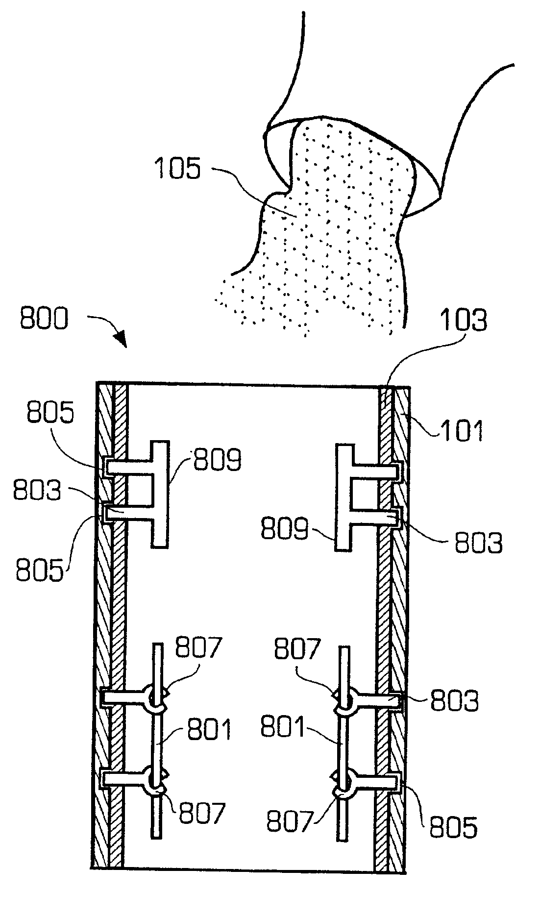
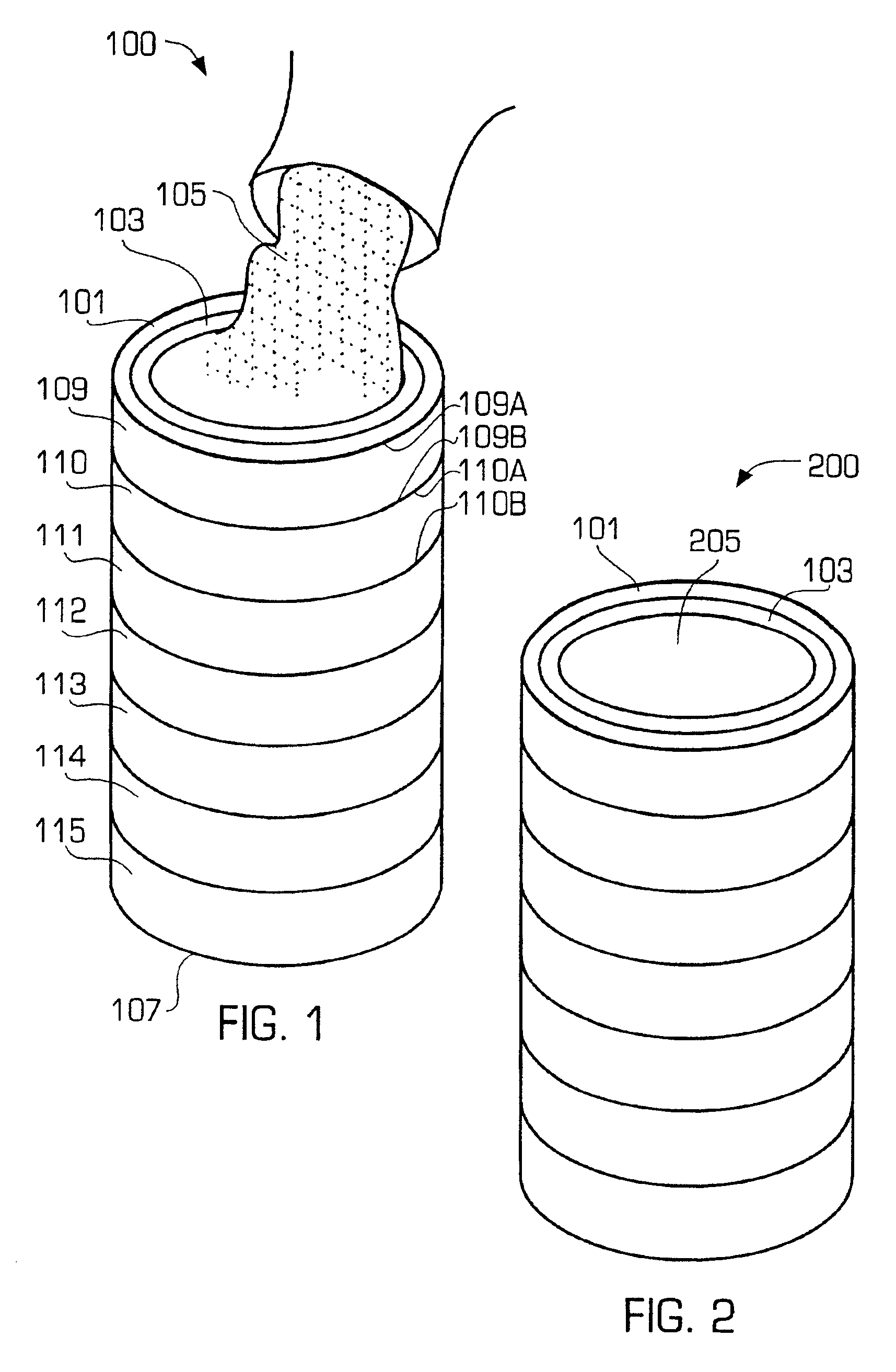
Referring to FIG. 1, a perspective view of a stay-in-place form 100 for use as a support structure, such as a column or beam, is shown. Although stay-in-place form 100 is illustrated as an elongate tubular structure in FIG. 1, it will be appreciated that stay-in-place form 100 may be any desired shape, such as rectangular or octagonal. Stay-in-place form 100 includes an exterior composite shell 101 and a liner 103 secured to the inner surface of composite shell 101. In this way, stay-in-place form 100 provides a hollow closed form into which a slurry of concrete or cement material 105 is placed. Slurry 105 fills stay-in-place form 100 and hardens to form a concrete core 205 of a fully reinforced support structure 200, illustrated in FIG. 2.

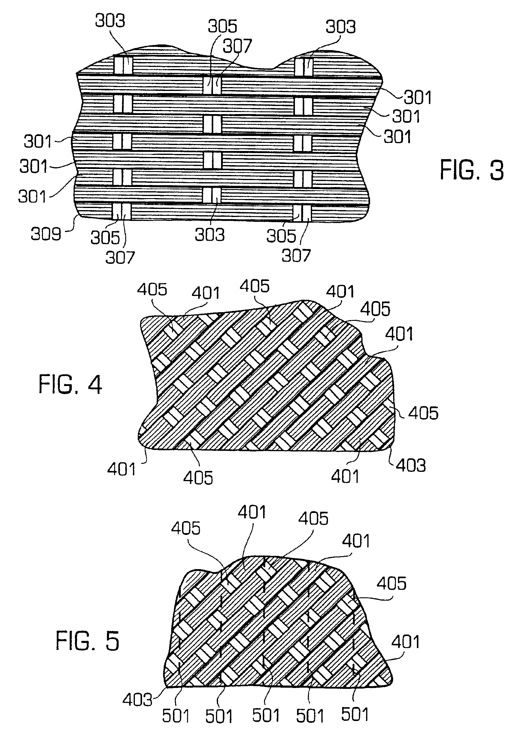
Composite shell 101 is formed of a resin-impregnated composite reinforcement layer 107, as illustrated in FIG. 1. Composite reinforcement layer 300 is in direct contact with the outer surface of liner 103 and may be made of a sin...


PUM

PropertyMeasurementUnit
Weightaaaaaaaaaa
Shrinkageaaaaaaaaaa
Elongationaaaaaaaaaa

Abstract

A stay-in-place method of manufacturing a composite form that is used to provide a strong and durable concrete structure. The form includes a composite shell having an inner wall surface defining an enclosure into which concrete may be poured and allowed to harden. The composite shell may be made of one or several layers of fabric having a resin matrix impregnated therein. The concrete hardens to form a concrete core within the enclosure and a liner is affixed to the inner wall surface of the composite shell to protect the composite shell from alkalinity in the concrete core. The liner includes at least one sheet of a water-impermeable material to protect the concrete core from water and other corrosive elements. The fabric layers are selected such that the fibers elongate as the concrete is poured into the enclosure due to a weight of the concrete and partially shrink back to compensate for shrinkage of the concrete as the concrete dries to form the concrete core. Such stay-in-place composite form can be used in prefabricated form to strengthen new constructions.

Description

BACKGROUND OF THE INVENTION1. Technical Field of the InventionThis invention relates generally to concrete support structures and in particular, to stay-in-place forms (i.e., composite shells) for forming concrete support structures.2. Description of the Related ArtConcrete columns are commonly used as upright supports for superstructures. Bridge supports, freeway overpass supports, building structural supports and parking structure supports are just a few of the many uses for concrete columns. Other concrete support members such as beams, walls, slabs, girders, struts, braces, etc. are employed to impart strength and stability to a large variety of structures. These concrete support structures exist in a wide variety of shapes. Typically, these concrete support structures have circular, square or rectangular cross-sections. However, numerous other cross-sectional shapes have been used including regular polygonal shapes and irregular cross-sections. The size of the concrete support ...

Claims


Application Information

Patent Timeline
IPC IPC(8): E04C3/30E04C5/07E04C3/34
CPCE04C5/07E04C3/34
Inventor FYFE, EDWARD ROBERT
Owner FYFE
Why Eureka
Try Eureka