Process for removing mercury from flue gases

a technology of flue gas and mercury, which is applied in the direction of separation processes, dispersed particle separation, chemistry apparatus and processes, etc., can solve the problems of high additional capital costs, insufficient effectiveness of previous techniques for reducing mercury, and strict limiting values for legally permissible mercury emission, etc., and achieves the effect of inexpensive operation

Inactive Publication Date: 2005-04-12
BROMERC
View PDF12 Cites 379 Cited by
  • Summary
  • Abstract
  • Description
  • Claims
  • Application Information

AI Technical Summary

Benefits of technology

to provide a process for removing mercury, in particular for the substantially complete removal of mercury (Hg), from flue gases of high-temperature processes. The process is to find the broadest possible application, as in the case of essentially constant low Hg concentrations, for example in coal-fired power stations, but also in the case of relatively high Hg concentrati...

Problems solved by technology

Owing to the high toxicity of mercury, in particular of organically bound mercury, which is also absorbed by humans directly or indirectly via the food chain, strict limiting values exist for the legally permissible emission of mercury, for ex...

Method used


Image

  • Process for removing mercury from flue gases
  • Process for removing mercury from flue gases
  • Process for removing mercury from flue gases

Examples


examples

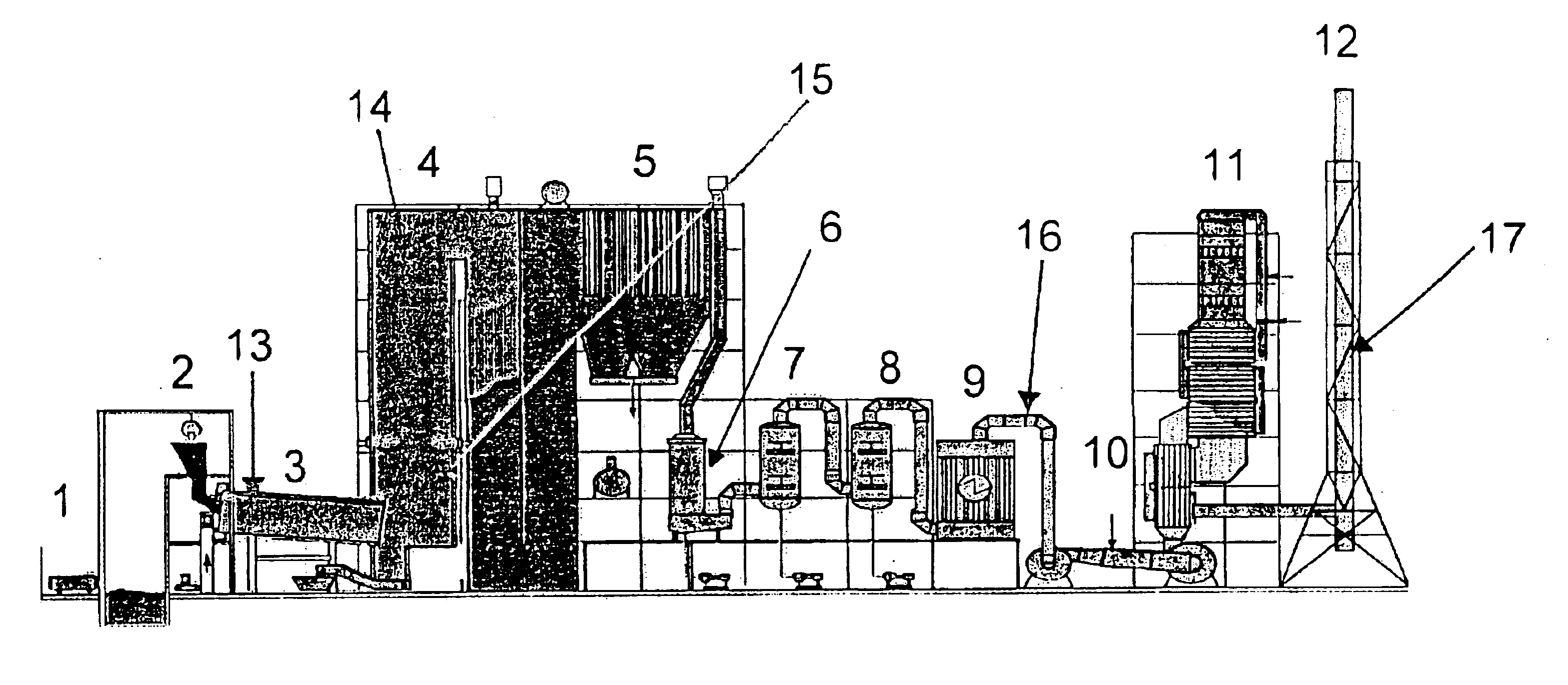
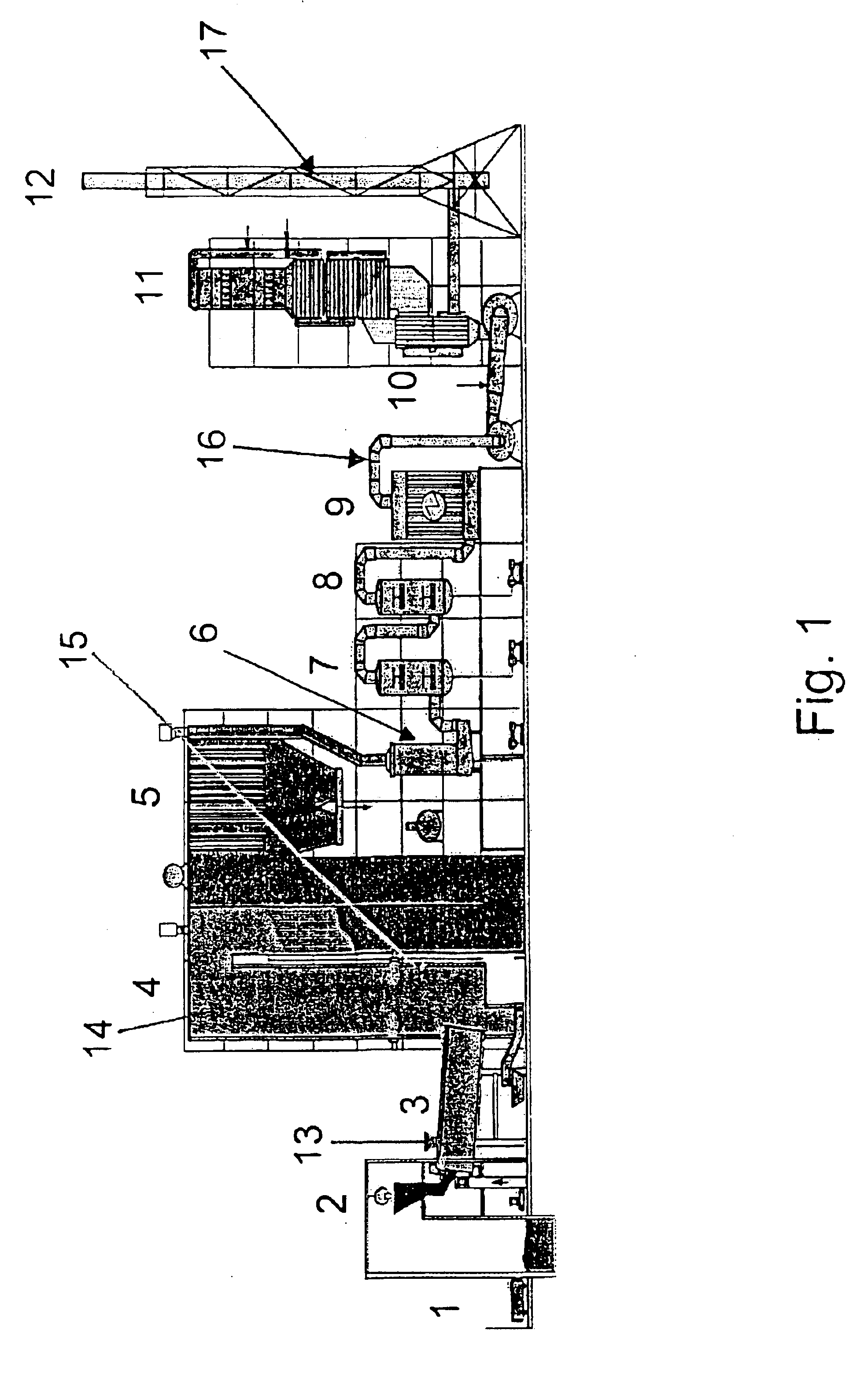
Examples 1-4 have been carried out in a special hazardous incineration plant of Bayer AG in Leverkusen corresponding to the diagram in FIG. 1. The rotary kiln 3 as primary combustion chamber is fired with solid waste from the bunker 1 via a crane grab 2, with liquid waste from a liquid waste tank and with waste drams via a dram feeder. The afterburning chamber 4, as a secondary combustion chamber, is also fired with liquid waste. The flue gas is cooled via the waste-heat boiler 5 and then, as what is termed dirty boiler gas, fed to the wet flue gas emission control system (multistage scrubber), which encompasses a quench 6, an acid rotary atomizer scrubber 7, an alkaline rotary atomizer scrubber 8 and an electrostatic gas cleanup system involving partial condensation of steam 9. Via suction fans 10 the scrubbed dirty gas, as what is termed clean gas, passes into the downstream catalytic denitrification plant 11 (selective catalytic denitrification of the clean gas by means of ammoni...

example 1

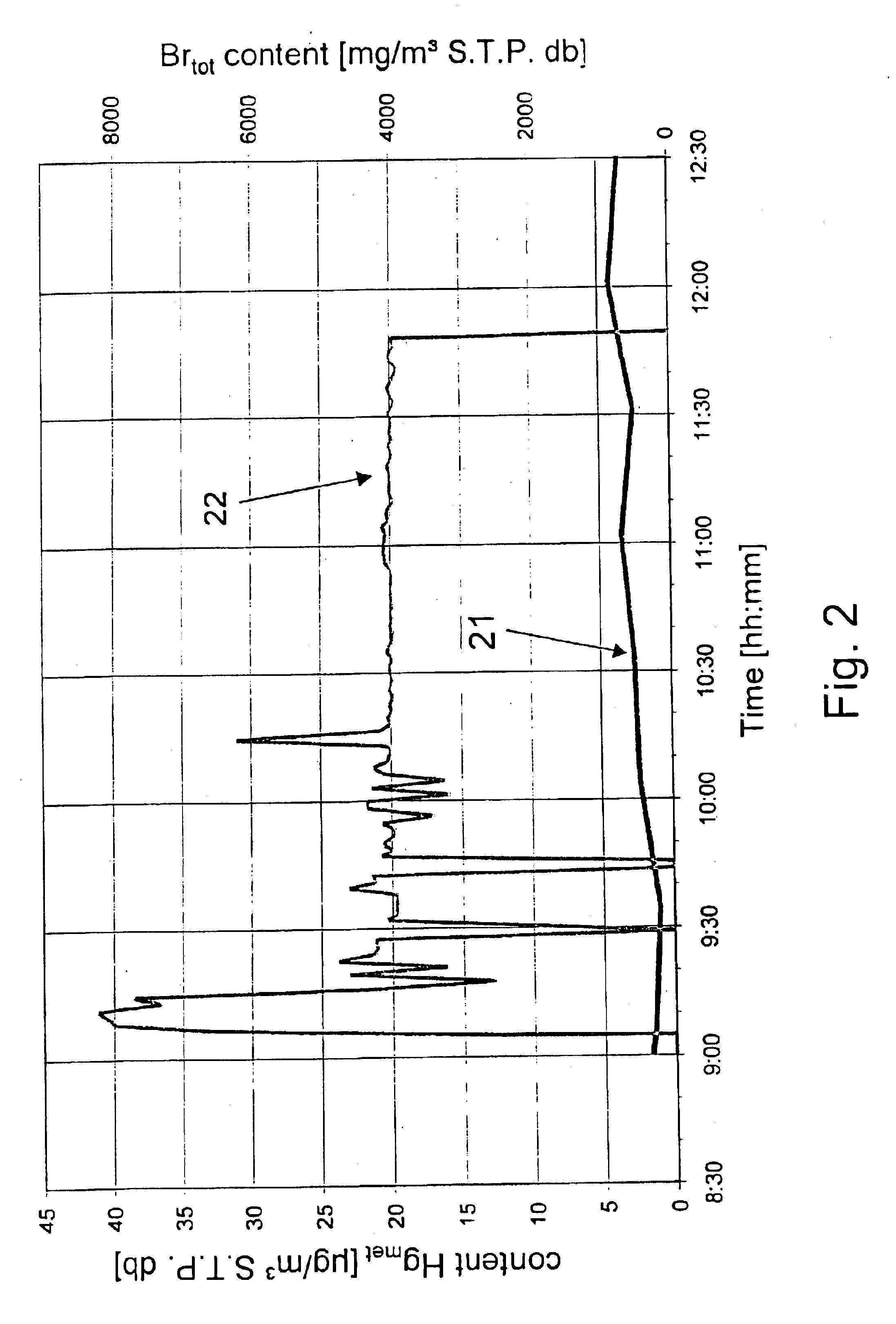
Over a period of 116 minutes, a series of samples of metallic mercury in plastic capsules (in total 3400 g, see Table 1) were fed to the secondary combustion chamber (afterburning chamber 4) via the inspection port 15. The feed was performed at intervals of approximately 5-10 minutes with increasing amount of mercury. The mercury introduced vaporizes within approximately 2-4 minutes; therefore, the instantaneous peak mercury concentrations occurring in the boiler flue gas at a volume flow rate of approximately 45·103 m3 S.T.P. db / h can be estimated. The estimation at the end of the experiment gives peak mercury concentrations of more than 130·103 μg / m3 S.T.P. db.

TABLE 1Addition of Hg samplesTimeHg amount [g]TimeHg amount [g] 9:24510:32180 9:321010:37200 9:381510:43220 9:492010:48240 9:544010:53260 9:596010:5828010:048011:0330010:0910011:0831010:1512011:1332010:2014011:2034010:26160Experimental time [min]Total Hg amount [g]1163400

During the experimental period, by co-combustion of a ...

example 2

Over a period of 130 minutes, an aqueous HgCl2 solution was fed continuously to the secondary combustion chamber (afterburning chamber 4) via a nozzle in the afterburning chamber roof. The rate added was increased here at intervals of about 5 minutes. FIG. 3 shows the increase in mercury concentration thus induced in the boiler flue gas in the time between approximately 10:45 and 13:00. The mercury introduced is immediately released in the afterburning chamber as metallic mercury Hgmet. The total mercury concentration in the boiler flue gas increased in this manner to values of 18·103 μg / m3 S.T.P db (curve 31 and left y axis). The Hg concentration in the boiler flue gas was calculated from the mercury addition rate and the flue gas volume flow rate measured operationally. During the experimental period, by co-incineration of a highly brominated liquid waste (addition via a burner at the rotary kiln head) a bromine content of approximately 9·103 mg / m3 S.T.P. db was maintained in the ...


PUM

PropertyMeasurementUnit
Temperatureaaaaaaaaaa

Abstract

Process for removing mercury from flue gases of high-temperature plants, in particular power stations and waste incineration plants in which a bromine compound is fed to the multistage furnace and/or the flue gas in a plant section downstream of the furnace, the temperature during contact of the bromine compound with the flue gas being at least 500° C., preferably at least 800° C. The combustion is carried out in the presence of a sulphur compound, in particular sulphur dioxide. Subsequently to the furnace, the flue gas is subjected to an optional multistage cleanup for removing mercury from the flue gas, which cleanup comprises a wet scrubber and/or a dry cleanup.

Description

The invention relates to a process for removing mercury from flue gases of high-temperature plants, in particular power stations and waste incineration plants.BACKGROUND OF THE INVENTIONOwing to the high toxicity of mercury, in particular of organically bound mercury, which is also absorbed by humans directly or indirectly via the food chain, strict limiting values exist for the legally permissible emission of mercury, for example from incineration plants and power stations. Despite the currently already low mercury concentrations of clean gas,—the half-hourly mean value currently permissible in Germany for mercury emissions from waste incineration plants is 30 μg / m3 S.T.P. dry basis (S.T.P. db),—owing to high volumetric flow rates, for example from large power stations, considerable mercury loadings are achieved, so that further reduction of the currently permitted limiting values is sought.A range of processes for reducing mercury emissions from power stations, waste incineration ...

Claims


Application Information

Patent Timeline
IPC IPC(8): B01D53/46B01D53/64
CPCB01D53/64
Inventor VOSTEEN, BERNHARDBEYER, JOACHIMBONKHOFER, THEODORE-GERHARDFLETH, OLAFWIELAND, ANDREAPOHONTSCH, ANDREASKANEFKE, RICOSTANDAU, EWAMUELLER, CLAUSNOLTE, MICHAELKOESER, HEINZ
Owner BROMERC
Why Eureka
Try Eureka