Differential measurement system based on the use of pairs of Bragg gratings

a measurement system and bragg grating technology, applied in the field of measurement systems, can solve the problems of noise inducing the signal measured, complex and expensive techniques, and further limitations in the technique with regard to acquisition frequency

Inactive Publication Date: 2005-04-12
COMMISSARIAT A LENERGIE ATOMIQUE ET AUX ENERGIES ALTERNATIVES
View PDF5 Cites 12 Cited by
  • Summary
  • Abstract
  • Description
  • Claims
  • Application Information

AI Technical Summary

Benefits of technology

These two gratings are overall identical, except with regard to their spectral sensitivities (relative to the quantity to be measured) which are slightly different from each other. Joint analysis of the two gratings thus allows a differential measurement which does not require an accurate spectral analysis.
The system which is the subject of the invention enables several types of physical quantities to be measured, in particular temperatures, stresses and pressures and this, in a less expensive way than the known techniques mentioned above.
According to another particular embodiment, the two Bragg gratings have different sheaths making it possible to adjust their sensitivity with respect to each parameter to be measured.

Problems solved by technology

Furthermore, the technique described in document [2] uses chirped gratings which are fairly difficult to manufacture and susceptible to strain because of their length, thus inducing noise on the signal measured.
It is a complex and expensive technique since it requires the use of an optical spectrum analyser.
This technique is further limited with regard to the acquisition frequencies.

Method used


Image

  • Differential measurement system based on the use of pairs of Bragg gratings
  • Differential measurement system based on the use of pairs of Bragg gratings
  • Differential measurement system based on the use of pairs of Bragg gratings

Examples


Embodiment Construction

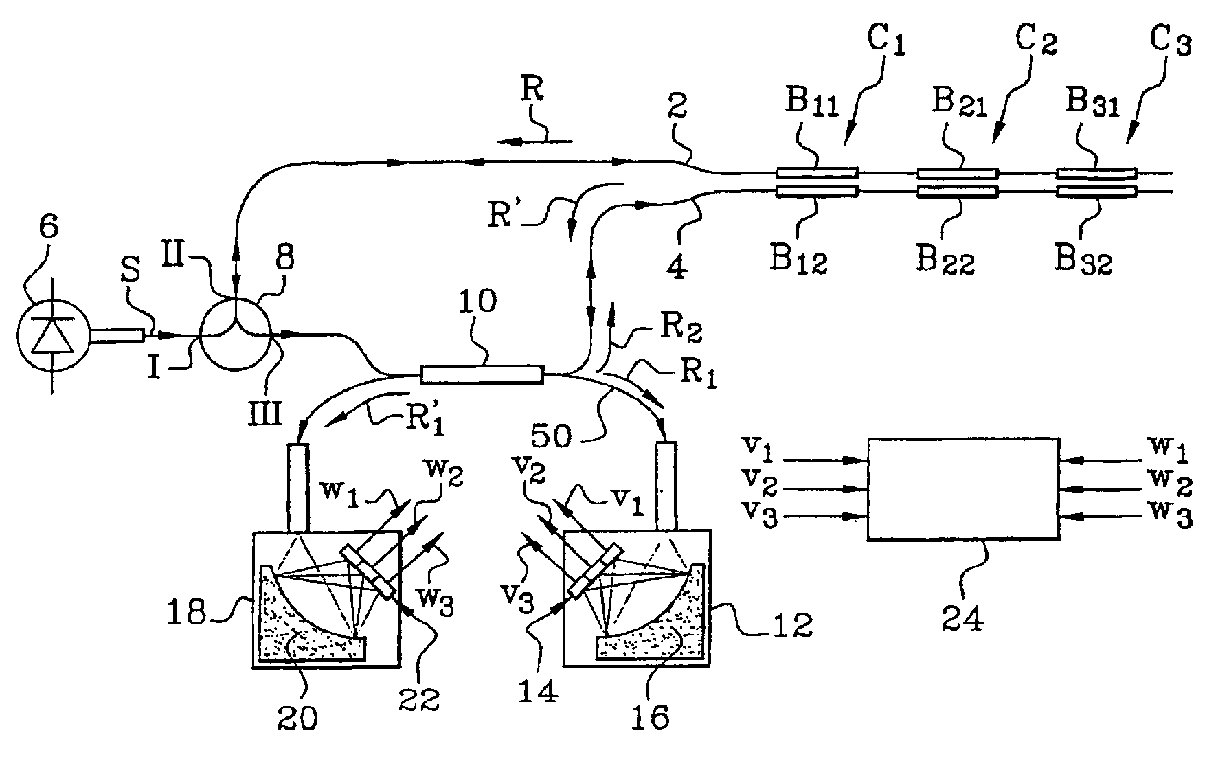
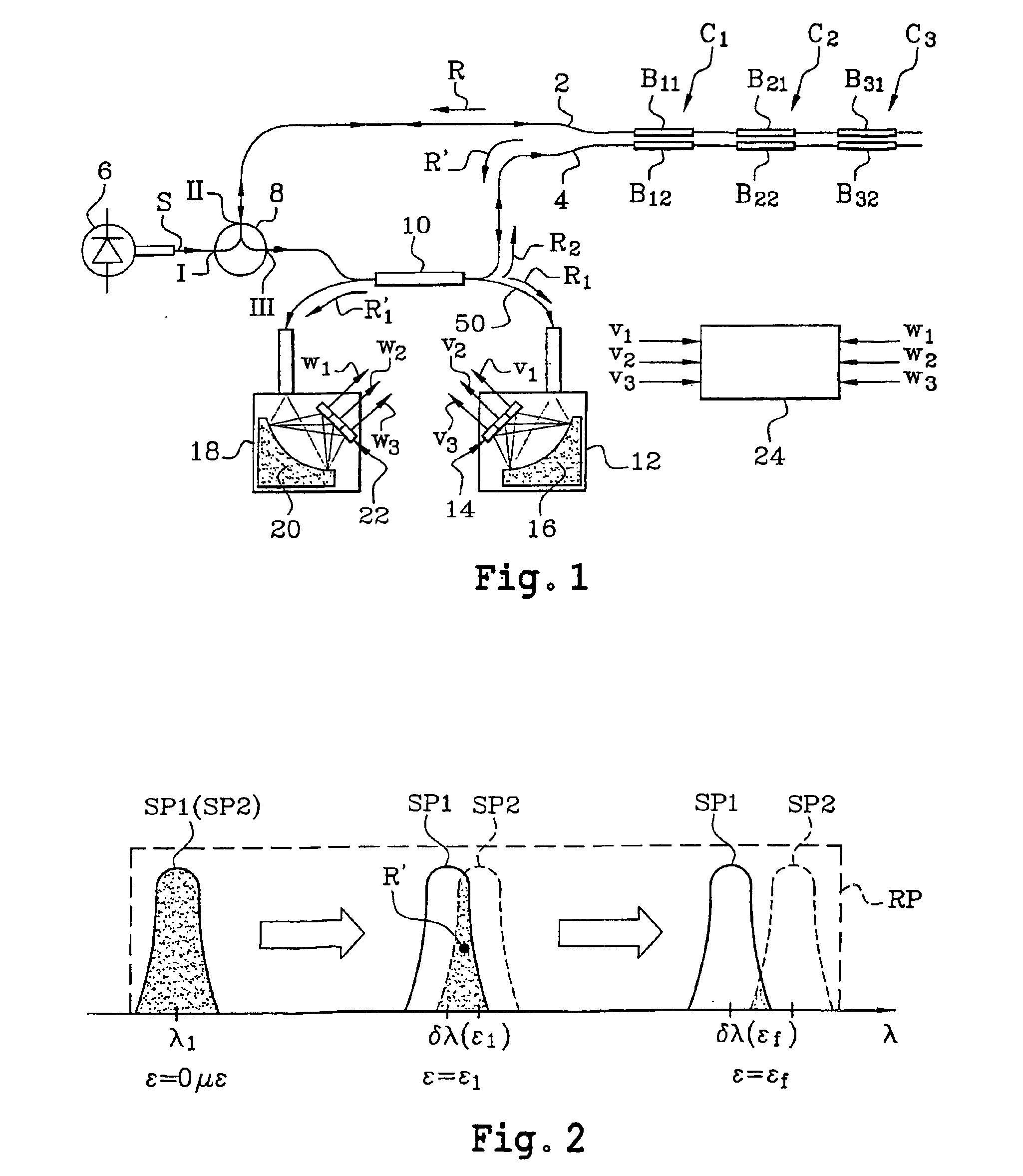
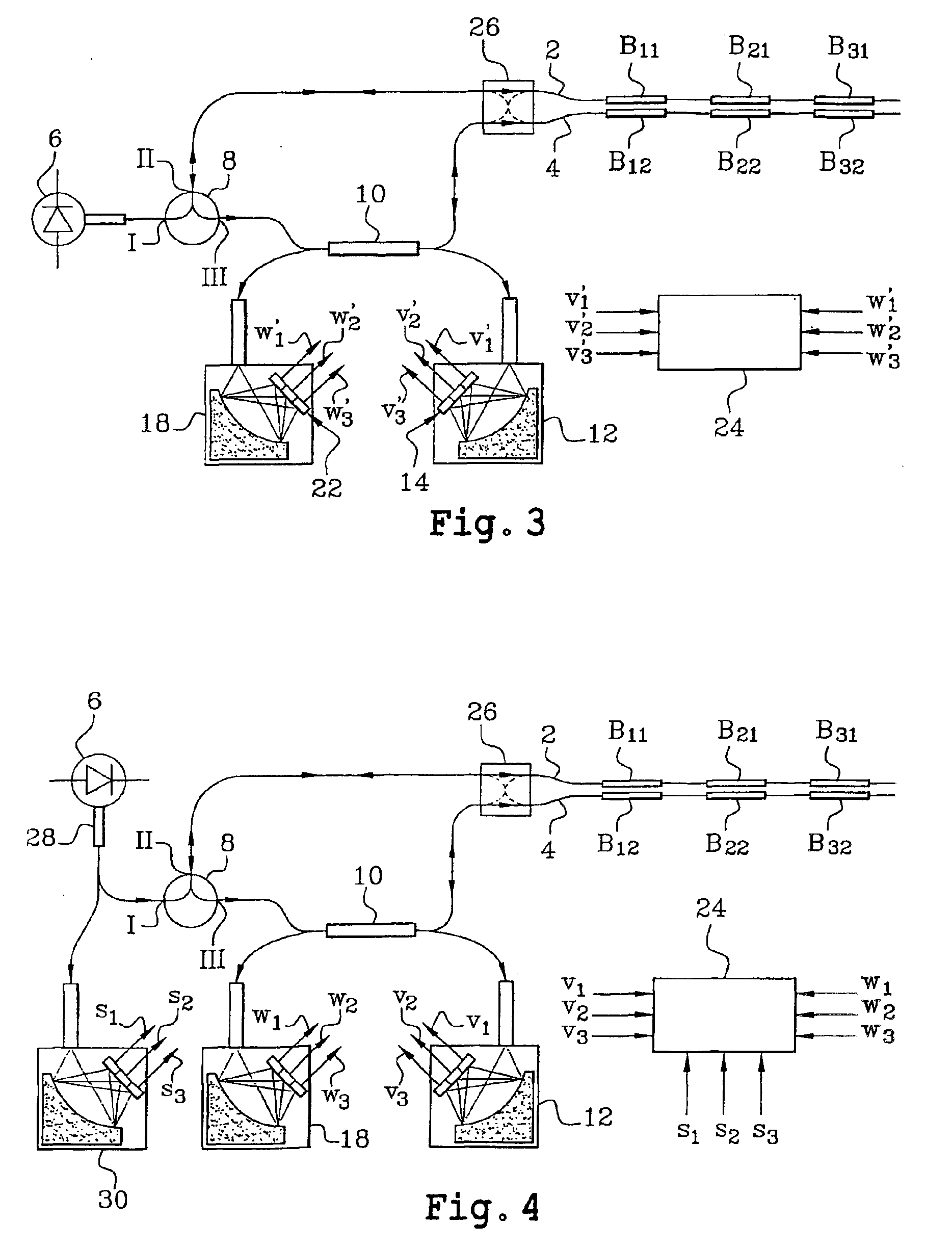
One example of the system which is the subject of the invention is schematically shown in FIG. 1. In this example, three sensors C1, C2 and C3 are used. The sensor C1 (or C2, C3 respectively) comprises two Bragg gratings B11, B12 (or B21, B22 or B31, B32 respectively) each forming a transducer.

The Bragg gratings B11, B21 and B31 (or B12, B22 and B32, respectively) are formed in an optical fibre 2 (or 4, respectively).

The Bragg gratings B11 and B12 have a resonant wavelength λ1, the Bragg gratings B21 and B22, a resonant wavelength λ2 and the Bragg gratings B31 and B32, a resonant wavelength λ3.

At the input to this system, there is first of all a broadband fibre optical source 6, emitting in the infrared, typically around 1.5 μm (but any other spectral band could be used). The spectral bandwidth of the source 6 depends on the number of sensors to be interrogated.

If, by way of example, a spectral variation of 10 nm is allowed on each transducer (which is equivalent to a 1% extension o...


PUM

PropertyMeasurementUnit
power levelaaaaaaaaaa
power levelsaaaaaaaaaa
resonant wavelengthsaaaaaaaaaa

Abstract

A differential measurement system using pairs of Bragg gratings including at least one optical sensor having two Bragg gratings in two optical waveguides and having sensitivities adjusted so that respective spectra of the two gratings have a relative spectral shift dependent on a parameter or parameters to be measured. The system also includes an optical source to supply light to the two optical waveguides to interrogate them, a mechanism enabling light to pass successively through the two Bragg gratings of the same sensor, photodetectors to measure the power level of light having passed only through one of the two optical waveguides and the power level of light having passed successively through the two optical waveguides, and a processor to process the power levels and supply values of the parameter or parameters measured. The system is applicable in particular to measurements of temperatures, stresses, and pressures.

Description

TECHNICAL FIELDThe present invention relates to a measurement system which uses Bragg gratings.In particular, it is applicable to measurements of temperatures, stresses and pressures.DESCRIPTION OF THE PRIOR ARTReference may be made to the following documents:[1] D. A. Jackson, A. B. Lobo Ribeiro, L. Reekie and J. L. Archambault, “Simple multiplexing scheme for a fibre-optic grating sensor network” Optics Letters, Vol. 19(14), 1993, pp 1192-1194[2] R. W. Fallon, L. Zhang, A. Gloag and I. Bennion, “Identical broadband chirped grating interrogation technique for temperature and strain sensing” Electronics Letters, Vol. 33(8), 1997, pp 705-707[3] L. A. Ferreira, F. M. Araujo, J. L. Santos and F. Farahi, “Temperature and strain insensitive bend measurements with D-type fibre Bragg gratings” OFS (Optical Fibre Sensors) Conference 14, WE 2—2, Venice, October 2000.Documents [1] and [2] disclose measurement techniques which use Bragg gratings and which are based on analysing the overlap of ...

Claims


Application Information

Patent Timeline
Patent Type & Authority Patents(United States)
IPC IPC(8): G01D5/353G01D5/26G01L1/24G01K11/12
CPCG01L1/246G01D5/35383
Inventor MARTINEZ, CHRISTOPHEFERDINAND, PIERRE
Owner COMMISSARIAT A LENERGIE ATOMIQUE ET AUX ENERGIES ALTERNATIVES
Why Eureka
Try Eureka