
Photosensor system and drive control method thereof

a technology of drive control and photosensor, which is applied in the field of photosensor system, can solve the problems of inability to set a proper charge accumulation period, and inability to so as to prevent any malfunction in setting the reading sensitivity and accurately read a subject image

Inactive Publication Date: 2005-04-12
CASIO COMPUTER CO LTD
View PDF21 Cites 65 Cited by
  • Summary
  • Abstract
  • Description
  • Claims
  • Application Information

AI Technical Summary

Benefits of technology

[0020]It is an object of the present invention to provide a reading sensitivity setting method of uniquely and automatically setting a proper reading sensitivity on the basis of read results obtained immediately before the start of normal reading operation of a subject image in order to accurately read a subject image in various use environments in a photosensor system having a photosensor array constituted by two-dimensionally arraying a plurality of photosensors. It is another object of the present invention to prevent any malfunction in setting the reading sensitivity even if a foreign substance attaches to the sensing surface of a photosensor, or a photosensor element becomes defective.
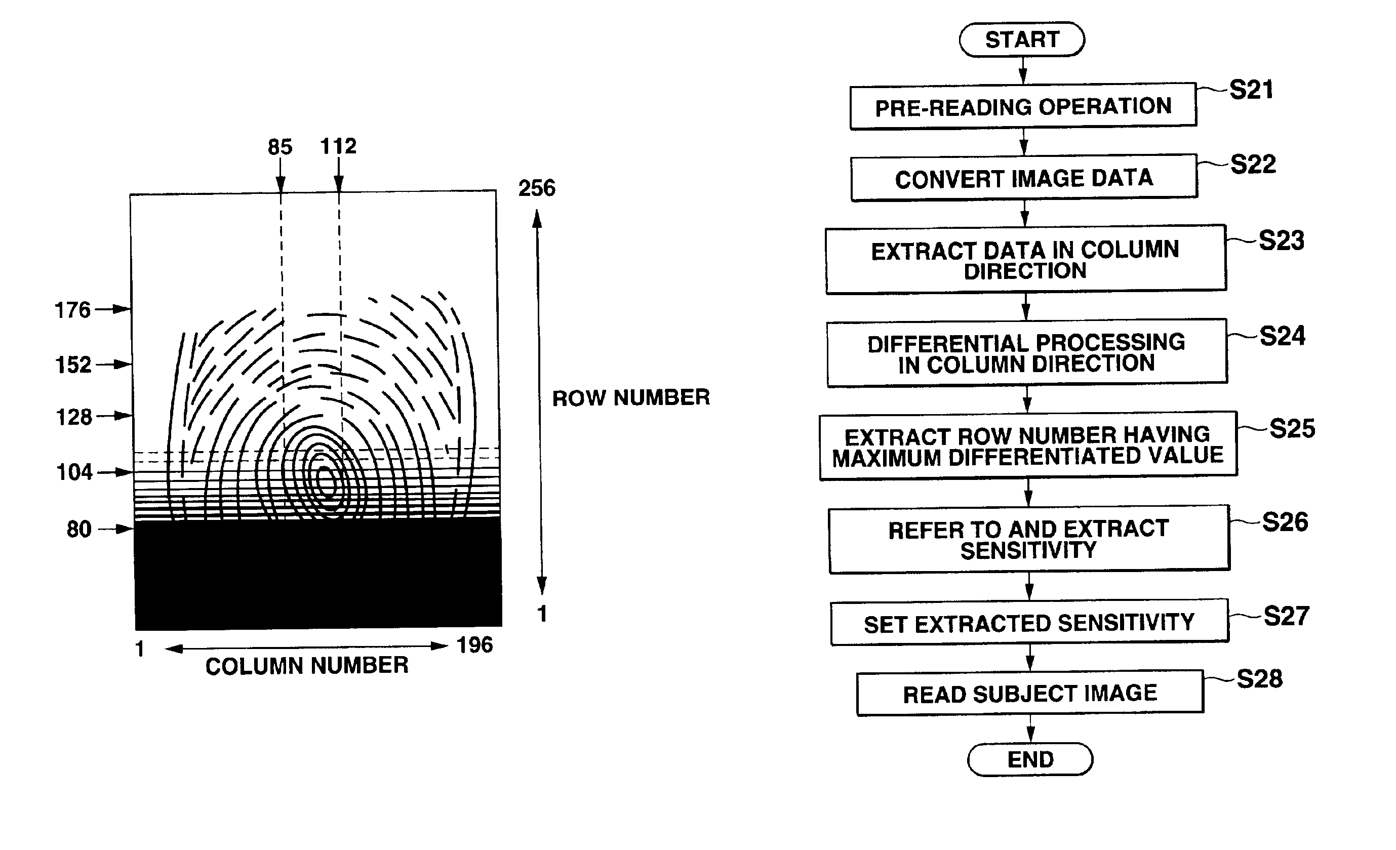
[0022]To achieve the above objects, according to the first reading sensitivity setting method of the present invention, pre-reading operation of changing the charge accumulating period at a plurality of stages for, e.g., respective rows is executed before the start of normal reading operation of a subject image. A row in which the dynamic range of lightness data for each row is maximum, or a row in which the displacement (differentiated value) of lightness data between rows in a specific column direction is maximum is extracted from read image data. An image reading sensitivity set for the extracted row is set as an optimal sensitivity. This can reduce the data amount to be processed, simplify sensitivity setting processing, and shorten the required time. Even when the ambient light or the characteristics of the photosensor change, an optimal image reading sensitivity can be set in accordance with the changes.
[0023]To achieve the above objects, according to the second reading sensitivity setting method of the present invention, pre-reading operation of changing the charge accumulating period at a plurality of stages for, e.g., respective rows is executed before the start of normal reading operation of a subject image. A row in which the dynamic range is maximum and the linearly differentiated value of the dynamic range is minimum is extracted from the dynamic ranges of lightness data of read image data for respective rows, or the dynamic ranges of lightness data for respective rows from which high-frequency components upon changes in the dynamic ranges of the rows are removed. An image reading sensitivity set for the extracted row is set as an optimal sensitivity. A row corresponding to an appropriate image reading sensitivity can be extracted without any influence of an abnormal pixel generated by a foreign substance attached to the sensing surface of the photosensor array, a defect of the photosensor element, or the like. The present invention can provide a reliable reading sensitivity setting method.

Problems solved by technology

(1) To read a subject image in various use environments in a photosensor system using the above-described photosensor, the reading sensitivity (charge accumulating period) must be properly set. The proper charge accumulating period changes depending on changes in ambient conditions such as the illuminance of external light in a use environment, and also changes when the characteristics of the photosensor change. In the prior art, therefore, a circuit for detecting the illuminance of external light must be additionally arranged. Alternatively, reading operation (to be referred to as pre-reading operation hereinafter) of changing the charge accumulating periods to a plurality of stages before the start of normal reading operation of a subject image must be executed to obtain the optimal value of the charge accumulating period from the read result. However, a reading sensitivity setting method of uniquely and automatically setting a proper charge accumulating period based on a read result every charge accumulating period that is obtained by pre-reading operation has not been developed yet.
(2) If a foreign substance attaches to the sensing surface of a photosensor or a defect is generated in a photosensor element in setting the reading sensitivity based on the result of pre-reading operation, and a read result obtained every charge accumulating period by pre-reading operation is directly used, an abnormal value is contained in the read result to fail in setting a proper charge accumulating period and inhibiting accurate reading operation of a subject image. For example, when this photosensor system is applied to a fingerprint reading apparatus, the apparatus may malfunction in fingerprint recognition processing.

Method used


Image

  • Photosensor system and drive control method thereof
  • Photosensor system and drive control method thereof
  • Photosensor system and drive control method thereof

Examples


fifth embodiment

[0053]FIG. 27B is a graph showing the dynamic range distribution of lightness data of respective rows after abnormal value removing operation in the fifth embodiment;

first embodiment

[0054]FIGS. 28A to 28J are timing charts showing an image reading sensitivity setting method applied to pre-reading operation in each embodiment;

second embodiment

[0055]FIGS. 29A to 29J are timing charts showing an image reading sensitivity setting method applied to pre-reading operation in each embodiment;

[0056]FIGS. 30A to 30H are timing charts showing an embodiment when an effective voltage adjusting period is set after pre-reading and image reading periods in a photosensor system drive control method according to the present invention;

[0057]FIG. 31A is a sectional view showing the structure of a conventional double-gate photosensor;

[0058]FIG. 31B is an equivalent circuit diagram showing the double-gate photosensor;

[0059]FIG. 32 is a schematic view showing a photosensor system constituted by two-dimensionally arraying double-gate photosensors; and

[0060]FIGS. 33A to 33D are timing charts showing a conventional drive method for the double-gate photosensor system.

DETAILED DESCRIPTION OF THE INVENTION

[0061]Methods of controlling a photosensor system according to the present invention will be described in detail with reference to the several vi...


PUM


Abstract

A photosensor system is provided which includes a photosensor array constituted by two-dimensionally arraying a plurality of photosensors, a driver circuit for supplying a drive signal to the photosensors, and a controller for controlling a reading operation of a subject image and a sensitivity setting. Before the start of normal reading operation of a subject image, a pre-reading operation of changing the image reading sensitivity at a plurality of stages for respective rows is executed. A row in an optimal image reading state is easily determined based on the dynamic range distribution of the lightness data of read image data or a dynamic range distribution from which an abnormal value deviating from the main change trend of lightness data is removed, and the linearly differentiated value of the dynamic range. An image reading sensitivity set for this row is set as an optimal sensitivity.

Description

CROSS-REFERENCE TO RELATED APPLICATIONS[0002]This application is based upon and claims the benefit of priority from the prior Japanese Patent Applications No. 11-316650, filed Nov. 8, 1999; No. 11-319605, filed Nov. 10, 1999; and No. 2000-015981, filed Jan. 25, 2000, the entire contents of which are incorporated herein by reference.BACKGROUND OF THE INVENTION[0003]The present invention relates to a photosensor system having a photosensor array constituted by two-dimensionally arraying a plurality of photosensors, and a drive control method thereof.[0004]Imaging apparatuses such as electronic still cameras, video cameras, and the like have come to be very widely used. These imaging apparatuses employ a solid-state imaging device, such as a CCD (Charge Coupled Device), which serves as a photoelectric converting device for converting an image of a to-be-photographed subject into an image signal. As well known, the CCD has a structure in which photosensors (light receiving elements) suc...

Claims


Application Information

Patent Timeline
IPC IPC(8): H04N5/235H04N3/15H04N5/353H04N5/367
CPCH04N5/2351H04N5/3675H04N5/3535H04N5/353H04N23/71H04N25/53H04N25/533H04N25/683
Inventor NAKAMURA, YOSHIAKIKOSHIZUKA, YASUO
Owner CASIO COMPUTER CO LTD
Learn More